-
Notifications
You must be signed in to change notification settings - Fork 5
Auto Network Coding
Editing networks requires an understanding of the model inputs as described on the Networks and Zone Data page. You should familiarize yourself with the various elements that make up the network before editing. You should also be familiar with network editing in VISUM before attempting to modify the network.
Typically network editing involves adding, deleting, or modifying nodes and links. Whenever you add, delete, or modify a link, you need to make sure that all of the required values in the Link Attributes table are populated.
Unlike a traditional trip-based model, which has one zone system, the ABM has three zone systems. Since VISUM’s network data model only supports one zone system for skimming and assignment, the VISUM Zones need to be changed on-the-fly from TAZs to MAZs or TAPs. This means that each version file created during the model run may have a different set of zones and connectors depending on the purpose. Thus, it is important to always start with the input master version file when making editing since it contains all three zone systems. The VISUM Zones are TAZs, the VISUM MainZones are MAZs, and the VISUM StopAreas are TAPs.
The ABM model network is based off a NAVTEQ network that includes local and in some locations even private roads. Therefore, given the overall scale of the model network, all manual network coding is only performed for roadways and intersections containing at least a collector classification street or greater (arterial, ramp, interstate).
The following specific link attributes must be coded onto the network for the volume-delay function (VDF) works properly:
- FromNodeNo: The "from" node
- ToNodeNo: The "to" node
- TypeNo: The VDF link type (set by the code, not the user)
- TSysSet: Allowed transportation system modes
- FFSPEED: Free-flow speed (internal calculation field set by the code, not the user)
- PlanNo: Link facility type
- Toll_PrTSys(DSEG): The toll for each demand segment in $2010 dollars (typically 0)
- NumLanes: The number of through or mid-block lanes
- AUX_LANES: The number of auxiliary lanes on freeways
- MEDIAN: Type of median
In addition to link attributes, a number of intersection (node) attributes must be reviewed and properly coded in order to properly capture intersection capacities. Please see Intersection Coding below for specific details. For additional information on how the VDF is calculating delay, please see the VDF Definition page.
The following section describes how to code various aspects of the auto network.
“MEDIAN” should be populated with an integer between 0 and 3, indicating the following treatments: - 0 = No Median - 1 = Raised Median (Jersey Barrier, curb, or raised pavement area) - 2 = Striped Median (Hatched painted median shadow, etc.) - 3 = Two-Way-Left Turn Lane (TWLTL)
Currently, the volume-delay function does not differentiate between the different median treatments; it only matters whether there is a median or not.
Examples of each of the four median treatments are shown below.

“AUX_LANES” should be populated with an integer representing the number of auxiliary lanes along a freeway segment. Note that the auxiliary lanes should not be included in the Visum “Lanes” attribute, but only in the “AUX_LANES” attribute. An example of a freeway auxiliary lane is shown below. Note that there are no auxiliary lanes in the base-year SOABM auto network.

Intersection edits focus on the Node and Turns Visum network elements. The following four VDF attributes should be coded at the intersections (nodes or main nodes) for all intersections that include a minimum collector classification or higher:
- Intersection control type
- Direction of free flow or major movement (unsignalized intersections or two-way stop only)
- Lane lengths (signalized intersections only)
- Intersection Configurations (signalized intersections only)
In addition, some intersections require special attention due to separated through links. These intersections are addressed with Main Nodes, as discussed in a following section.
Intersection control type can be identified from base-year Google Earth aerial imagery or based on traffic engineering judgment for future facilities. The following types of intersection control are coded on the Visum node “ControlType” attribute:
- Signalized
- All-way stop
- Two-way stop
- Two-way yield
- Roundabout
- Uncontrolled
- Unknown (default)
The figure below shows examples of each type of control used in the ABM network.

For all signalized, two-way stop controlled, two-way yield controlled intersections, the free flow or major movement must be coded to correctly represent the correct traffic control condition. The free flow direction is coded using the “Major Flow Manually” tool in the Visum Junction Editor. The figure below shows how to use the “Major Flow Manually” too to code the free-flow movement correctly at a two-way stop controlled intersection.

Signalized intersections require additional network detail, including auxiliary turn lanes and storage lengths. The lane data is coded into the turn attributes from the junction editor, which is opened by double-clicking on the target node while in editing mode. The figure below shows an example how to code additional lanes and lane lengths at an intersection using the junction editor.

In additional to turn lanes and storage lengths, the ABM model requires all signalized intersections to have the correct allowed movements. The allowed movements for a specific lane can be visualized for editing with the following steps:
- Open junction editor for the target intersection (node)
- Click on the “Geometry” tab of the junction editor viewer (this typically opens in a separate view from the junction editor itself)
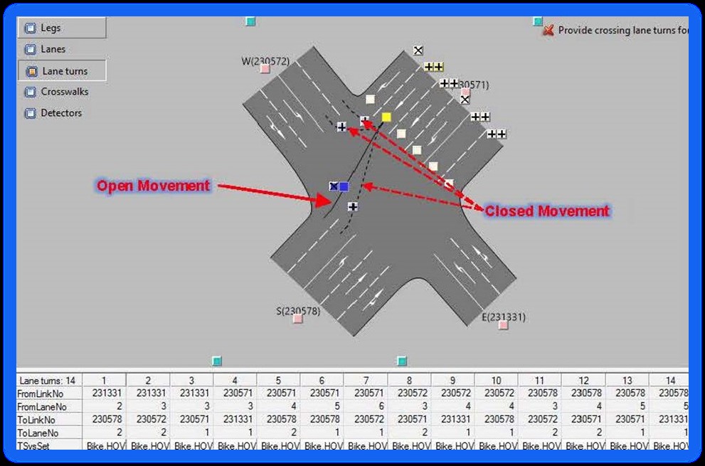
- Click on the “Lane turns” tab within the junction editor window (see figure below)
- Click on the “Mark leg” button (the pink square) on the approach leg where you wish to edit
- Visualize the allowed movements for a specific lane by clicking on the “Mark movement” button (white box, turns yellow when active for editing)
- Use the “x” button to close and the “+” button to open an allowed movement.
All movements are allowed by default when they do not conflict with another allowed movement on their approach leg. A dashed line represents a closed movement, and a solid line represents an open movement. When opening and closing allowed movements, be cautious of which buttons are associated with each movement. Zoom in on the movements for better visualization. Note that by default the network should be set to close U-turns when editing.

In several locations throughout the ABM network, links are separated by direction at intersections. This situation typically occurs on major arterials with raised medians. In these locations, the Visum “Main Node” network elements are used to consolidate the signalized intersections to the appropriate movements required for the VDF functions. The figure below shows an example of how to apply a main node to an intersection with links separated by direction of traffic flow.

Overall, Main Node coding should follow the same guidelines as outlined for regular node intersections, using the Visum “ControlType” attribute to indicated signalized intersections, and adding turn lanes and modifying movements in the Main Node junction editor. However, Main Nodes do have added complexity. Some key editing guidelines include:
- Only include nodes directly associated with intersection movements within the Main Node boundary. Accidentally including any nodes that simply split links (shaping nodes) will prevent correct movement editing and result display after the run.
- Make sure that the control type is set to “unknown” for all nodes within the Main Node boundary. Only the Main Node is assigned the field control type (Signalized, Two-way Stop, etc.)
- U-turn movement are typically allowed by default for a main node on all approaches with multiple links. Unless the intersection allows for U-turns in real life, these allowed movements should be closed.
More detail on “Main Node” editing can be found in Section 15.20 (pages 1208 – 1231) of the PTV Visum 18 – Manual.
After editing the auto or non-motorized network, it is a good idea to check network connectivity. To do so, run the following steps:
- Go to Calculate + Network Check
- Unclick all the procedure except for Check network consistency between “All zones” for each transport system edited
- Run the procedure
- Click the ! to review the errors (i.e. OD pairs that are not connected)
- Close Calculate + Network Check
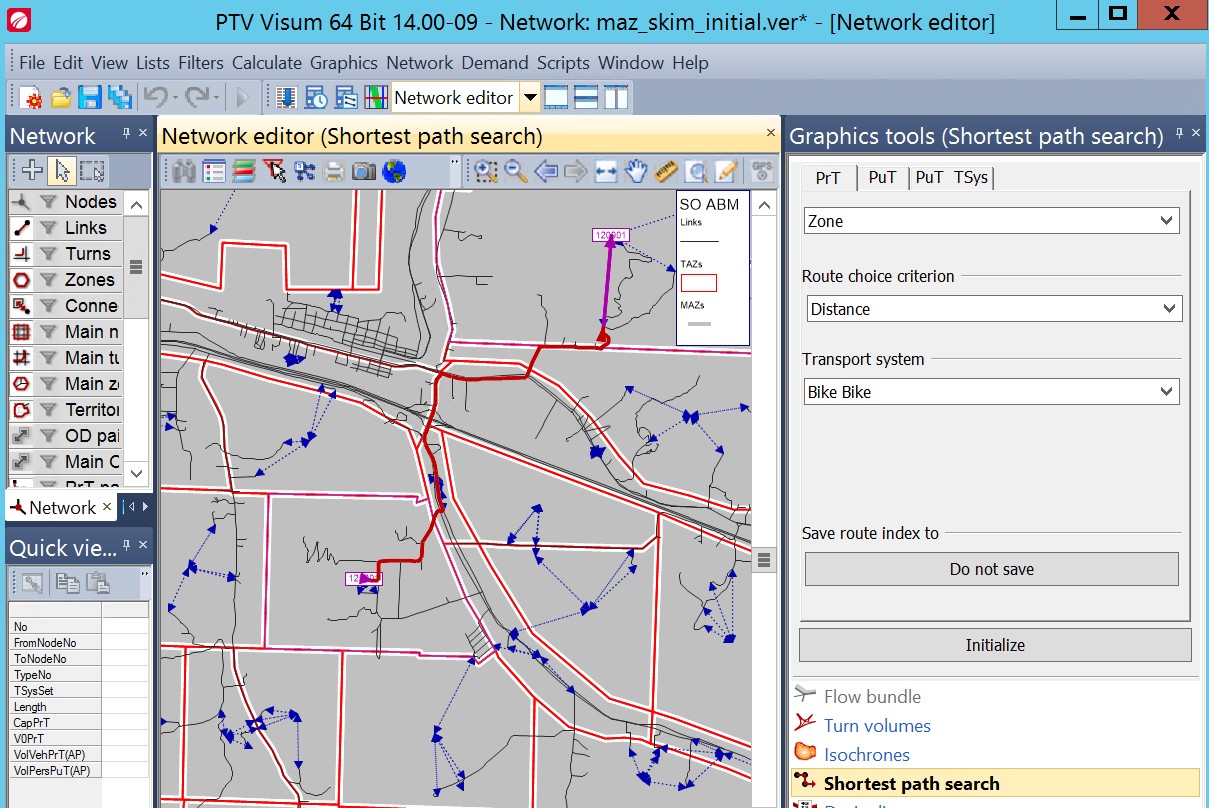
- Go To Graphics + Shortest Path Search (Network Shortest Path Search Check)
- Try to find a shortest path for the transport system edited for an OD pair that is not connected. Use distance for walk and bike and t0 for auto modes.
- Work from the origin zone or destination zone toward the other end of the trip to find the unconnected links, turns, or nodes.
- Repair the connection and repeat until all OD pairs are connected.

The highway network is shown in below, with a detailed view of Medford and Grants Pass also shown.
 VISUM HIGHWAY NETWORK
 MEDFORD HIGHWAY NETWORK
 GRANTS PASS HIGHWAY NETWORK
- Getting Started
- RunModel bat file
- Networks and Zone Data
- Auto Network Coding
- VDF Definition
- Transit Network Coding
- Non-motorized Network Coding
- Editing Land Use Data
- Running the Population Synthesizer
- Input Checker
- Analyzing Model Outputs
- Commercial Vehicle Model
- External Model
- Model Cost Inputs
- Value of Time
- Person Type Coding Logic
- MSA Feedback
- VMT Computation
- Shadow Pricing Mechanism
- Methodology for Developing TAZ Boundaries
- Methodology for Developing MAZ Boundaries
- Methodology for Developing TAPS
- Source of Land-Use Inputs
- Major University Model (Optional)
- Running Transit Everywhere Scenario
- Building the ABM Java Program
- Debugging ABM Python Code
- ABM Cleaning Protocol
- Updating to New Visum
- Troubleshooting and Debugging