Transit Network Coding
There are several inter-related components that are used to represent transit accessibility and level-of-service in the ABM.
- Line Routes: The transit routes that are coded on the auto network to represent the transit route alignment, stop locations, frequency, and fare.
- Lines: Transit lines, with no required attributes. The line name is currently set to the Google transit operator and route number. The available Transport Systems for transit lines are Bus, Commuter Rail, Express Bus, and Light Rail.
- Stop Points: Used to represent the boarding and alighting points for each transit route. No required attributes.
- Stop Areas (TAPs): Transit Access Points (TAPs). Centroids that are used to represent the location of transit stops in the ABM software (see description below)
- Non-motorized (walk) network: Used to find the walk path from each MAZ to each TAP
- Auto network: Used for the calculation of travel times for non-fixed guideway transit routes, based on the congested auto speed.
Before attempting to edit transit networks, it is important to understand how transit skimming and assignment works in the ABM. Unlike many trip-based models, the ABM uses Transit Access Points (TAPs) as 'dummy' zone centroids for transit skims. TAPs are centroids that represent one or more transit stops. For the ABM model, all stops were used as TAPs since there were less than 500 total stops in the transit network. However, TAPs do not necessarily have to be coded uniquely for each stop; one TAP can be connected to multiple stops.
The VISUM stop model (shown below) is used as follows: 1) stop points – transit stop locations, 2) stop areas – TAPs, and 3) stops – groups of stop areas for virtual transferring.
Transit walk transferring is also allowed by the assignment and skimming procedures if desired.
Since Stop Areas are converted to VISUM zones for TAP skimming and assignment, a stop area to nearest network node connector is built on-the-fly.

FIGURE 4 - VISUM STOP MODEL
Transit skims are built between TAPs instead of TAZs, and transit walk and drive times are automatically calculated by Python scripts between each MAZ and TAP within a certain distance. Three sets of transit skims are built:
- Set 1: 'Local only': This TAP set only includes local bus
- Set 2: 'Premium only': This TAP set only includes premium (express bus, Bus Rapid Transit, Light Rail Transit, Commuter Rail) modes.
- Set 3: 'Local plus premium': This TAP set includes both local and premium modes. Any TAP pair without both local bus and premium (at least one transfer between the two modes) is zeroed out.
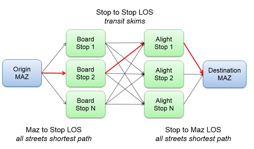
The three TAP skim sets are skimmed in order to maximize the variation in transit paths found between each TAP pair. The ABM software reads the three sets of TAP skims and the distances and times between each MAZ and each TAP it is accessible to. The accessibility, tour, and trip mode choice components of the software use this data to calculate the transit mode choice logsum, and if transit is chosen at the trip level, the boarding and alighting TAP pair is selected from one of the three skim sets. See the figure below for a graphical depiction of 'virtual path building' in the model.
There are three steps to calculating transit utility in tour and trip mode choice models:
- Step 1: TAP-Pair Ranking: The transit utility is calculated for each boarding TAP and alighting TAP within walk or drive access of the origin and destination MAZ. The access and egress utilities are calculated based on the walk and drive times between the MAZs and the TAPs, while the TAP-to-TAP utility from the first boarding TAP to the last alighting TAP are calculated from the skims. The access, egress, and TAP-to-TAP utilities are added together to calculate the total transit utility for each TAP-pair. The four best TAP-pairs are retained for each trip, regardless of which TAP skim they are in. The ranking procedure uses generic coefficients that do not vary by person or purpose.
- Step 2: Transit Utility Calculation: The transit utility is recalculated based on person and/or model-specific coefficients. For example, tour coefficients are used to calculate a transit utility for each TAP-pair to be used in the logsum calculation for the tour mode choice models, while trip mode choice coefficients are used to calculate utilities for the trip mode choice models.
- Step 3: Transit Logsum Calculation: A transit logsum is calculated across the best TAP pairs and used in mode choice models.
If transit is chosen in the trip mode choice model, a TAP pair is selected from the best TAP pairs according to the probability of selection of each TAP Pair. The first boarding\last alighting TAP and the skim set that the TAP pair was selected from is written out to the trip file, and the trip is added to the appropriate matrix for transit assignment.
To code a new route in the transit network, follow these steps:
- Open your scenario version file
- Select Lines from the Network Table of Contents and Insert object (i.e. the plus sign) in the Network Editor
- Click on the map to create a Line, set the Name, and set the Transport System (most commonly Bus)
- Click on the map to create a Line Route, select the new Line, and set the Name. Currently all routes are coded as round-trip; if coding a new route using this convention, use default Direction.
- Edit the course of the line route by clicking-and-dragging from the start node to intermediate nodes to the final node. Make sure to check the Parameters for settings related to routing through closed links, turns, not active stops, etc. Remember that Line Routes are coded through Stop Points, which are connected to Stop Areas, which are connected to Nodes. The model TAPs are VISUM Stop Areas.
- After editing the line route, switch to select mode (i.e. the arrow) in the Network Editor and select the new line route.
- Click on the Items and Time Profile tab and make sure there is a Time Profile (i.e. this tab is populated with run and dwell times between stops). These should be calculated based on link travel times for the transit mode and can be updated as needed.
- Click on the User-defined attributes: Line route and set the headway for each time period in seconds.
- The final step is to run a transit assignment to check for boardings and/or alightings at each stop for each new line to ensure the new service is available.
If you are going to complete these steps it is assumed that you have already acquired or developed a set of transit lines in GTFS format. If you have a GTFS dataset that you are planning to import into your ABM network (scenario) follow these steps:
- In Visum go to File -> Import -> General Transit Feed (GTFS). This will create a new Visum version file with just the GTFS transit lines (no highway network, models zones... just the GTFS lines).
- After the import is complete go to Network -> Network settings -> Calendar and choose "No calendar".
- Review the imported transit lines and remove any that are not intended to be added to the ABM network. Additionally, at this step the line and route naming should be reviewed and revised if the names from the GTFS import are not helpful (if hard to understand line codes were brought in instead of meaningful names, like the "red line" or "Route 61").
- Set the Coordinate System in the imported transit line file to the same coordinate system into the same coordinates that our in the ABM file which the transit lines will be imported into. To do this, first verify what Coordinate System the ABM network file is in (it should be OGIC), and then go to the transit line version file and ensure it is using the same Coordinate System using the following steps: Network -> Network settings -> Scale -> Co-ordinate system -> From file -> Projected Coordinate Systems -> State Systems -> OGIC
- If there are only select transit lines to import, filter out only desired lines using the following steps: Filter Lines -> Vehicle journey section [tab] -> Attribute equal VehJourney\LineName and set that filter equal to whatever line is desired to be imported. If multiple lines are desired multiple line filters can be added using the same VehJourney\LineName filter. Create multiple filter statements under the vehicle journey section tab and use "or" statements for each line. Another option is to delete all undesired lines. If all lines are desired to be imported, this filter step is not needed.
- Save the transit line edits in the imported GTFS version file and close the version file.
- Open the Visum file for the ABM network that the GTFS lines are intended to be imported to.
- Choose File -> Import -> PuT supply from Visum.
- PTV has provided ODOT with a template file for with recommended settings to consider when importing transit lines. The file name is currently named "PuT_Import.puti" and can be provided as requested. If this file is going to be used, the first step will be to "Open parameters" in the "PuT supply from Visum" window and load the provided file.
- Whether a parameter file is loaded or not, the next step is to chose (browse to) the GTFS version file that was saved above in step 5.
- There are many parameters in this import feature, for full detail on these settings please refer to Visum's user guide. While lots of good information exists in the user guide, many of these parameters will likely not be needed. Here are some to consider, several of which are addressed when loading the parameter file discussed in step 8:
- choose whether to add the new lines in addition to the lines already coded on the ABM network (not making a change to the defaults), or
- to fully replace all the lines in the ABM network with the new GTFS import, in which case the user would check the box for "Replace or delete active lines in the target network". Note that the user can select specific lines to delete from the network, by pre-selecting (making active) specific lines to delete before going to the import tool and then choosing this option. This choice relates to the decisions made in the steps above in prepping the transit lines file to import.
- Another default that will likely need to be adjusted is under the "Transport systems" tab. The transportation systems from the GTFS import version file may not align (be equal to) the transportation system options in the ABM. If the two version files have different naming (categories) for the transportation systems, the linkage (correspondence table) between the two needs to be set on the "Transportation systems" tab.
- Other parameters to consider (that are addressed in the provided *.puti parameter file):
- Under the "Stop points" tab choose "Also add stop points in target network on existing notes and links". If you happen to have a file where the new transit lines to be imported use the same stop system as exists on the current network, the user can choose "Assign stop points via attribute comparison" and select the attributes to join on.
- Under the "Routing" tab choose "Routing only via open links". Set snapping radius to something smaller than the default. Suggested values are between 50-75ft, this might require some testing.
- It's likely that warnings will generate after the import is started, those will need to be addressed accordingly and may require some iteration / testing. Potentially working in both the original Transit line file being imported and the ABM file receiving the import. Some examples:
- It could be that the import could be simplified by renaming transit lines, making slight edits or shifts to stop locations, or only selecting a few transit lines to import at a time. These would all be edits that can be done within the transit line file prior to the import.
- For the ABM file receiving the import, the user may need to allow the bus (transit) mode to travel on all links that cars are allowed to travel on. In some cases the network may currently only allow buses on links that have current transit lines. In those cases the user will likely want to open bus travel to all links where cars are allowed to travel as these are commonly viable links for buses and bus routes as well. Additionally, some parking lot or neighborhood links may be added to the ABM network prior to the import to help the new lines properly route. Examples of this can be airports or large malls, where the bus line may have a stop far off the road network at a mall door or airport terminal. In these cases it will likely improve the overall transit import to add those routes to to the stop location at these major destinations.
- After the import is complete the new lines should be manually reviewed on the ABM network looking for important issues discussed throughout this page, including making sure that the lines properly stop at all desired TAPs (see TAP coding bullet 4).
- Review also needs to include:
- Reviewing and updating the line route headway attributes, and
- Reviewing and revising TAP placement and attributes (specifically park and ride)
- Fares should also be reviewed and possibly revised. Fares can be found in inputs\fares.csv. If new fare zones are going to be added, the Fare Zones, a TAP attribute, may need to be revised and revised.
- The final step is to run a transit assignment to check for boardings and/or alightings at each stop for each new line to ensure the new service is available.
To modify an existing route, use the network editing tools described above to change the route alignment, add or remove stop points, update the run and dwell times, and/or change the headway. After selecting the line route and entering the line route dialog, click Edit Course to revise the route.
To delete a transit route, use the select mode (i.e. the arrow) in the Network Editor, select the line in the line select dialog, and right click and choose Delete.
Line routes code the sequence of links and stop points for each line. The lines are currently coded as round trip line routes due to the Google transit import. Line routes can be coded by direction if desired.
The user must code the Transport System for each route. The available Transport Systems for transit lines are:
| Transportation System (TSys) | Description |
|---|---|
| Bus | Bus - typical fixed route transit |
| ComRail | Commuter Rail - heavy rail like Amtrak or TriMet's WES |
| ExpBus | Express Bus - express (or limited) bus service. Could also be used for Bus Rapid Transit (BRT) like LTD's EmX . |
| LightRail | Light Rail - dedicated right-of-way light rail (LRT) service like TriMet's MAX. Could also be used for BRT. |
VISUM skims the total in-vehicle time (IVT) for the entire path, as well as the IVT by Transport System (i.e. submode), and these IVT by transit submode skims are used in the demand model to make it possible to add submode utility components, such as IVT discounts for non-included attributes such as comfort and reliability. See the BestTransitPathUtility.xls UEC for more information.
Line routes must be coded with a headway attribute for each time period. The headway needs to be coded in seconds. If the line is not available in a time period, then set the headway to a very large number such as 99999. To update route headways by time of day go to the "Line Routes" listing and the five headway attributes as listed here.
Transit line run and dwell times are set automatically using congested link travel times. In cases where the transit line is coded on a non-auto link (e.g. fixed-guideway transit), the run and dwell time must be set manually for the line route. To check, or set, the transit route run and dwell times, do the following:
- Set Lines as the active network objects
- Switch the dialog to Line Routes and double click the line route of interest
- Switch to the Items and time profiles tab as shown in the figure below (this step is no longer needed as of Visum 2023).
- Make sure the Board, Alight, Stop time, and Run time values are as expected. It is important to do this after the Set Run and Dwell Times procedure is run by the TAP skimming and assignment procedures since it updates these values.

TAPs must be coded with the attributes listed in TAP (STOPAREA) Attributes. The Stop area ID is used as the TAP ID in SOABM. Note, due to limitations in the java code, TAP numbering needs to be limited to as small a number as possible, ideally the TAPs are fully sequential numbers (although this is not required). Using larger numbers for TAPs can increase model run times and potentially crash the model if the numbering is too high. Keep TAP numbers as low as is possible and practical. There can be multiple stop points per stop area in VISUM. Note that the ABM has multiple cases where stop points for different lines are at the same point, and these duplicate stop points are captured in a single stop area (TAP).
TAPs must be coded by the user in addition to the transit route, according to the following guidelines:
- Every stop in the transit network must be connected to one (and only one) TAP.
- Multiple stops can be connected to the same TAP, but the analyst should differentiate TAPs serving 'premium' transit services (express bus, bus rapid transit, light rail, etc.) from other services.
- TAPs should be coded relatively close to actual stop locations, in order to accurately represent walk access from the MAZ to the transit stop.
- Line Routes should be reviewed to ensure that they correctly cross (access) the Stops (TAPs) along their route. Riders can only access the transit line at the TAP, so if the line misses the TAP, that area won't have access to the line, even if it goes through there area.
The Grants Pass and Medford transit networks are shown below.
 GRANTS PASS TRANSIT NETWORK
 MEDFORD TRANSIT NETWORK