usb controller replacement
This is by far the trickiest and specialized step.
FT-991/A ships with a two-port Microchip USB2512BI USB Hub which in turn are connected to the Audio and CAT ports, with no free/available ports.
In order to be able to lodge your SDR inside the radio and use the existing hub, you must replace it with a 3 or 4 port variant, which are 100% compatible drop-in replacements for the USB2512BI hub. My design choice is the 4-port variant, USB2514BI.
The replacement requires a experienced technician and a Hot Air Rework Station. Do NOT try to do it yourself with your standard soldering iron unless you are some soldering übergod.
First of all, you will need to remove remove the radio's SCP Unit. Carefully detach the IF and REF coax cables, as well the flex cable connecting to the main unit. Store aside. ESD-Sensitive unit, blah blah, you know the drill. The yellow arrow points the IF input signal.
Note. The Radio can work normally without the SCP Unit, in case you need for some test.
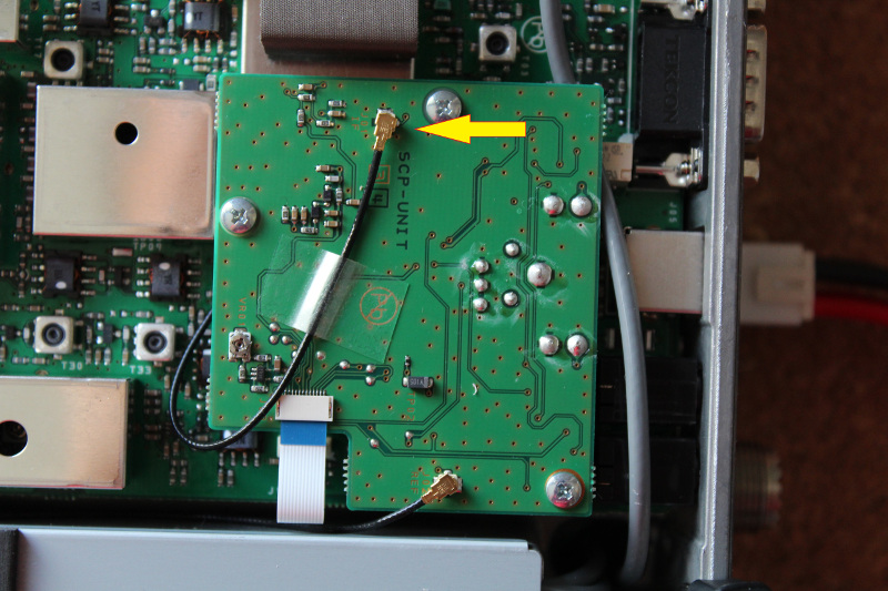
FT-991A SCP Unit
With the hot air, the IC is replaced in less than 5 minutes. Remember that this is a ESD-sensitive device and special precautions should be taken in order to avoid device damage.
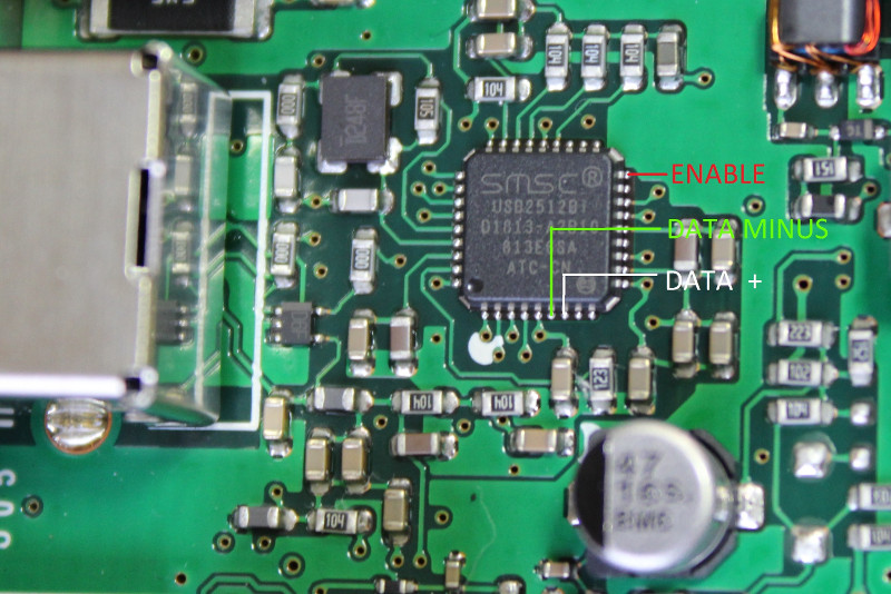
USB Controller and pins of interest - Hub Port 03
WARNING: this picture shows the ENABLE pin wired. It is NOT needed and not used in the current revision. Spare yourself the hassle of soldering it!!!
You WON'T want to run a cable straight off the new hub leads - These are tiny terminals and any minimal traction/stranding will immediately break the solder joint or even the chip's terminal - it is FRAGILE. And making the repair harder and harder (you can see from my pics…)
Instead, run a thin wire from each lead of interest and glue it on top of the chip. See below:
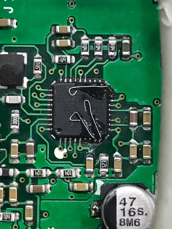
USB Controller and lead terminals - Hub Port 04
WARNING: this picture shows the ENABLE pin wired. It is NOT needed and not used in the current revision. Spare yourself the hassle of soldering it!!!
From here, make sure to anchor the wire somewhere else in the radio, so it won't move when you solder, move or work the cable's other side. Prefer a shielded cable.
IMPORTANT. Take the opportunity and solder at the other end of the wire a 22 Ohm resistor, on both USBDP (+, white) and USBDM (-, green) wires. The SDR won't be recognized by the computer/USB Hub if you miss this resistor.
After anchoring properly the wire, carefully and patiently solder it to the terminal that you prepared in the previous step. Make sure it is FINAL and avoid any kind of experimentation.