technical description
The objective of this project is to convert the FT-991A to a real SDR, providing I/Q output, centred in the radio's IF frequency (69.450 MHz), taking advantage of the radio's front-end pre-filtering, amplifiers, attenuators, Band-pass and Low pass filters - while not disturbing or desensitizing your radio RX stage. This project is built on top of the late G4HUP (SK) Panadapter Project Version 2.
The IF signal is tapped from the Scope Unit output (right after the RF switch prior to the roofing filters in non-A model), just before the Roofing filters.
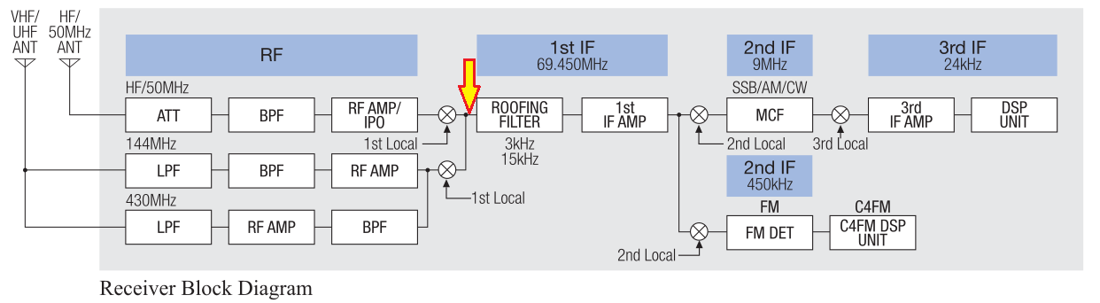
Radio Block Diagram and Tap point
In order to disrupt the IF signal to a minimum, the signal is tapped by a J310 FET, and subsequently fed to a 2SC5086 (EOLed, using BFR193 effective Revision S) low noise amplifier, which generates the signal to be sent to the SDR.
The board has provisions to only tap the signal when the radio is not transmitting, using the TX9 signal from the Radio. As soon the TX9 signal is present, the RF switch isolates the SDR, avoiding potentially strong signals that could damage your SDR.
This provides a good and steady 2.4 MHz-wide bandwidth which is enough to cover most of HF bands and good coverage of VHF and UHF bands within the 2.4 MHz bandwidth. The selected SDR for this project is a RTL-SDR Dongle Version 3 by Carl Laufer.

FT-991A Panadapter Board, Lite Version - Block diagram
I got a report of a successful deployment of SDRPlay RSP1A instead of the RTL-SDR, which provides stunning 6 MHz of bandwidth resolution.
In my implementation, I choose to actually lodge the SDR inside the radio, and expose it to the computer using the built-in USB Hub. It required the replacement of the built-in USB2512BI USB Hub with a USB2514BI 4-port variant, in order to get another extra USB port to connect the SDR. The pinout is exactly the same. Read more in Installation.
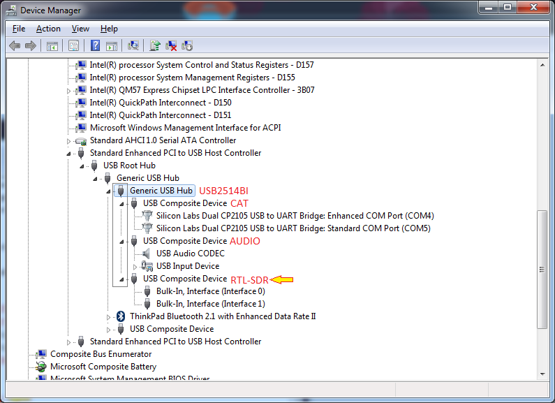
USB Enumeration of the Radio containing the Panadapter
The Full Version also sports a selectable 3 MHz Band-pass Filter centered around 70 MHz, in order to mitigate out-of-band interference and signal images in the Panadapter. The BPF is enabled by driving a 3V signal to the BPF pad in the board. By default, the signal skips the BPF. When the BPF is driven, the signal traverses a 3-pole Chebyshev Band-Pass filter, ~ 3 MHz wide. This feature is useful if you have out-of-band strong signals (broadcast, trunk radio, etc.) which causes RTL-SDR overload and spew images in the received spectra.
There is also a "Bypass" switch, which diverts the signal from the amplifier and moves straight to the SDR. Notice that it imposes a signal penalty to the Scope Unit - instead of having the IF signal 'tickling' the J310 FET, you are actually tapping it - translating to a -3dB decrease to the general IF signal - and causing to lose some sensitivity. Generally, you will not want to play with it, unless you really know what you are doing. Enable the "Bypass" mode by driving a 3V signal do the BYP pad in the board. The default setting is to put the signal through the amplifier (BYP off).
Finally, you can also manually inhibit the IF tap - By driving 3V to the DIS line. The RF switch grounds the SDR, separating and effectively isolating the Panadapter and the SDR from the IF line. You can also take advantage of the on-by-default GPIO 4 line from the SDR to keep the Panadapter isolated from the radio by default, enabling it on demand when you open your SDR software, by flipping the GPIO line state to low.

Panadapter, Full Version, Block diagram. Click to enlarge.