An TX/RX timer in a OLED display controlled by an Arduino
Compatible with Yaesu, Icom, Kenwood and other brands
This is a under $10 OLED on-air (TX) timer and RX (AF out), counting for how long you are transmitting, squelched or receiving a signal. It is compatible with every recent (in ham radio lingo, recent mean 20 last years) HF transceiver. It also prints for how long is your equipment turned on (uptime) in HH:MM format when not in transmit mode.
| Audio squelched | Playing audio (AF out) |
|---|---|
 |
 |
| Transmit mode | Transmit mode - exceeded TX time threshold |
|---|---|
 |
 |
| Audio squelched + Temperature Monitor | Playing audio (AF out) + Temperature Monitor |
|---|---|
 |
 |
It is controlled by the transceiver's Linear signaling port for the TX state, and the Squelch pin present in some radios to detect the RX AF out or squelched state.
When the radio enters transmit mode, the TX GND signal will bring the Arduino's GPIO line down to GND level, triggering the clock.
When the radio is receiving a signal (open squelch), the SQL line goes high to +5V and triggers the RX timer at the top right corner.
With no transmit and RX squelched, a squelch counter starts starts at the bottom left of the screen.
There's also a configuration that turns the screen dark in squelch mode and a small dot blinks at the right bottom corner of the display, as a watchdog.
A splashscreen is shown with your callsign (or your favourite text) on power-up.

The OLED timer - 6 seconds of TX time in a FT-991A
As a ragchewer, I miss a TX timer. I'm not talking about a TOT; but just to know how long have I been transmitting. And I'm now amused gauging how long are the 40m QSOs, heh.
Since Yaesu won't be providing me this anytime soon in their firmwares, I decided to give use to a Arduino sleeping in the drawer.
- Any Arduino board
- Jumper wire
- OLED display
- Adafruit SSD1306 and Adafruit GFX libraries
This is dead simple and any Arduino-compatible board should be up to the task - If you are using other Arduino variants, just remember to fix the pin numbers in the source code.
Below is a simplified schematic of the entire enterprise. Notice the resistors between GPIOs 2 & 13 and GND & 4. This is important.
In the TUN/LIN port use the TX GND pin for the TX and DATA/RTTY port SQL pin for RX.
In older Yaesu radios look for the BAND DATA, LINEAR, ACC, DATA, RTTY/PKT ports and check for the TX GND and SQL outputs and respective pinouts.

Yaesu equipment Connection diagram - click to enlarge
If your radio has the ACC or ACC1 socket, Use the SEND port for the TX signaling - Connect it to GPIO 2, and SQL S for RX signaling: Connect it to GPIO 4.
If your radio only has ACC2 ports, tap only the SEND signal.

Icom equipment Connection diagram - click to enlarge
Kenwood equipments does not provide a 13.8V port for powering the board - Tap it from your radio's power supply. Do not use an external wall wart for it; will add noise and ground loop funny business. No.
In ACC2 port, use the PSQ line and connect it to GPIO 4, since this is the Squelch signal. From the REMOTE port, use the LKY pin and connect it to GPIO 2 - this is the TX line.

Kenwood equipment Connection diagram - click to enlarge
-
Remember to put the arduino board in the same ground reference. Preferentially, use the radio's 13.8V output if available. Otherwise, tap from the power supply. Do not use an external power supply - Will surely just add noise to your radio and you don't want that.
-
For the TX timer, look for your Linear connection - there's a standard that the transceiver drive a pin to ground during TX. Tap this pin to GPIO 2.
-
Now for the RX, look for the squelch pin - not every radio provides it. Be sure to check the level as well; some signals the squelch open in a +5V (Yaesu), others (Kenwood and Icom) signals squelch open as GND level. DOUBLE CHECK THE VOLTAGE LEVEL - Your arduino will release the magic smoke if you drive more than 5 volt in the GPIO line!
The code provides support to the LM35 temperature sensor. In my usage, I have it attached to my transceiver chassis to monitor its temperature. Wiring it is super simple:
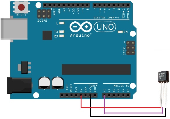
That's it. Just wiring the leads straight to the Arduino connector.
In order to sense target temperature in a bit longer distance, consider using headphone cable: Wire the copper mesh to ground, the red wire to +5V and the sensor output to the white wire. Wrap everything with thermal retractible isolator. Mine is one foot long and I have no problems with RF. See the below image:

There are a few configurable stuff in source code. Namely:
- The GPIO lines:
TX_GND- INPUT - The GPIO port receiving the radio'sTX_GNDPULLUP- OUTPUT - The GPIO port that will provide the +5V pull-up toTX_GNDRX_ON- INPUT - The GPIO port receiving the radio'sSQLsignal. Can be commented out to disable the RX counter.
- The threshold timer (
TIME_ALERT), can be commented out to disable - The callsign/text to be shown at power on (
CALLSIGN), can be commented out to disable - The temperature monitor is enabled by default. If you are not going to use it, ensure to comment out the line
#define TEMP_SENS
- It features a splash screen on power-on;
- Features a RX timer (smaller font size, in hh:mm:ss format). Only counts when squelch is open.
- The current system uptime is also printed during RX/Squelch time, at the top right of the screen (can be disabled)
- It also counts the squelched time (can be disabled).
- You can also configure a alert threshold - when your TX exceeds this transmission time, the display inverts color schema for extra warning.
Just don't forget the pull-up and pull-down resistors!!!
But you use the 13.8V output of the radio to power the arduino?
Yup. This line is rated 1.5A and is more than enough to power your Arduino. The Arduino Uno voltage regulator takes up to 15V. Use a choked cable, just in case, for bonus points. If using other Arduino variants, check the voltage regulator if can it take 13.8V.