Here is project of accessing 93LC86 EEPROM from CH341A USB to UART/IIC/SPI/TTL/ISP adapter EPP/MEM Parallel converter using SPI mode.
NOTE: The 93LC86 is actually Microwire device which is
similar to SPI but definitely not same.
There is nice Sigrok Microwire decoder page and it also includes
link to Microwire Specs
Here are key differences of Microwire 93LC86 from SPI:
CSpin is active on HIGH (typical SPI has/SS- slave select active in Low)- after each command the
CSpin must be deactivated and activated again - otherwise following commands will be ignored - after any programming command the
DO(orMISO) pin isREADY/BUSYpin which can be polled (even without clock). HoweverCSmay not be deactivated before this pin comes toREADYstate (otherwise this pin function is lost).
WARNING!
This project will overwrite data on connected 93LC86 EEPROM!
Current status:
- Basic READ and WRITE to 93LC86 EEPROM functions implemented The test program now does following:
- It writes and reads-back test value to/from EEPROM at address 1024 (0x400)
- It dumps contents of whole EEPROM to console
WARNING! Once my VirtualBox VM with XP SP3 (where I run my programs) suddenly rebooted. But it (fortunately) can't be reproduced again...
Circuit schematic is below:

Hardware:
- you need CH341A USB to UART/IIC/SPI/TTL/ISP adapter EPP/MEM Parallel converter I got my from Amazon.de as DollaTek CH341A USB zu UART/IIC/SPI/TTL/ISP Adapter EPP/MEM Parallelwandler. If you never used this module please see my article Getting started with LC CH341A USB conversion module
- EEPROM 93LC86, 100nF ceramic capacitor.
Software:
- Windows OS - I tested this project on Windows XP SP3 guest in VirtualBox
- Visual Studio 2010 (This it the last version supported on XP SP3)
The CH341A adapter must be setup following way:
- jumper set to
I2C/SPImode - voltage set to 5V TTL logic (to ensure highest possible speed and response of 93LC86
- please see picture below for correct configuration:

Software setup:
- Download and install CH341PAR.ZIP - USB driver for CH341 chip in Parallel mode (EPP, MEM). This driver is valid also for I2C mode and SPI mode (yes - even when it is marked parallel).
- install VisualSutdio 2010
Create environment variable CH341_SDK that should point to extracted
CH341PAR.ZIP header and library files. For example
if you have extracted file:
C:\CH341_DRIVER\LIB\C\CH341DLL.H
Then your CH341_SDK should be set to C:\CH341_DRIVER\LIB\C.
Open and rebuild solution VS2010_sol/ch341_spi_93lc86/ch341_spi_93lc86.sln
in VisualStudio 2010. There should be no errors.
Connect your CH341A USB module to target circuit. Following pins are used:
| PIN Name | Direction | Description |
|---|---|---|
| GND | N/A | Common ground |
| VCC | N/A | 5V supply |
| MISO | Input | master in slave out - SPI |
| MOSI | Output | master out slave in - SPI |
| SCK | Output | master clock - SPI |
| CS0 | Output | Chip select 0, active in high (93LC86 is Microwire but generally NOT SPI compatible) |
NOTE: Direction is from CH341A USB Module "view".
Connect your CH341 USB module to your PC. There should
be permanently lighting red LED on USB module.
The ch341dll.h API offers two interfaces for SPI:
- byte oriented
CH341SetStream()+CH341StreamSPI4()called for each byte. This is convenient API, but may not be flexible enough in complex scenarios (like this EEPROM) - bit-stream oriented
CH341Set_D5_D0()+CH341BitStreamSPI()called for each bit-set. Each byte represents (roughly) set of bitsD7toD0that have following meaning:
| Bit | Direction | Description |
|---|---|---|
| D7 | In | MISO - master in slave out data |
| D6 | In | SPI 5-wire pin? |
| D5 | Out | MOSI - master out slave in data |
| D4 | Out | SPI 5-wire pin? |
| D3 | Out | Clock (automatic cycle on each bit-stream byte transfer) |
| D2 | Out | CS2 |
| D1 | Out | CS1 |
| D0 | Out | CS0 |
WARNING: I'm unable to find reliable documentation on SPI 5-wire standard (common is SPI 4-wire).
WARNING: I did not verify above table (yet).
When you run compiled executable you should see messages like:
CH341 SPI shift register example
CH341 version: 33
Opening device# 0
DEBUG: WRITE succeed after 1 ms wait
DEBUG: WRITE succeed after 1 ms wait
Reading 2048 bytes from 93LC86...
Done. Data dump follows:
Dump of buffer at 0x0012F724,  bytes 2048

0x0000 90 30 10 b5 02 90 00 00 ff 00 00 01 04 0f 17 61 .0.............a
0x0010 00 00 00 40 00 00 00 00 48 01 48 01 00 00 00 00 [email protected].....
...
# here is test byte 0xab...
0x0400 ab ca ca ca ca ca ca ca ca ca ca ca ca ca ca ca ................
NOTE: you can see lots of 0xca bytes in my EEPROM because I already tried pattern write (WRAL) command on my STM32 Nucleo board
Please note that Reading whole EEPROM takes around 10 seconds on my VirtualBox VM
NOTES on USB: According to my current knowledge the USB PC<->CH341A adapter communication is done using packets with up to 32 instructions. The packets are send/received each 1ms or so (this is how such USB device works). Therefore there can be (and are) inherent delays.
Fortunately it is not problem, because there are no (low range) constraints on SPI master clock timings.
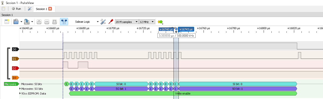
I finally found root cause why the PulseView's 93Cxx decoder did
not work. It was because 93LC86 is Microwire not SPI device
as described on Sigrok Microwire decoder page.
So now it works perfectly as can be seen here:

Thanks to PulseView Triggers it is incredibly easy to capture
start of communications (I just used rising edge trigger on channel
CH1 (shown as D0 in PulseView) and connected to CS0 signal.
NOTE: You need to run our exe program for the first time to ensure
that CS0 ends low before next run. And then starting trigger capture
in PulseView
Here are screenshots from whole WRITE cycle:
EWEN(Write Enable)WRITE(Write one byte)EWDS(Write disable)
So EWEN (Write Enable):
Followed by WRITE (Write one byte of data):

NOTE: The whole WRITE can't fit on screen because there is then large delay before remainder of data (cause by limited packet size on USB, followed by USB polling period - minimum 1ms for Full speed (does it applies for CH341A?).
And finally EWDS (Write Disable):

- only 8-bit data organization (
ORGpin Low) supported - the
HpCh_93c_Read()function does not utilize sequentialREAD(reading more than 1-byte in single command) - it would be faster. - the
BOOL HpCh_93c_SendCommand()function has hard limit of maximum total 32 transferred bits in whole command. - function
void HpCh_DumpBuf(BYTE *buf, int n)works correctly forndividable by16(or constantVALUES_PER_LINE) only.