This contains schematics for the dekatron clock I built. See it in action here:
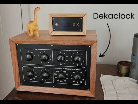
The clock uses no silicon - from power supply to all the logic involved, it uses vaccuum tubes and cold cathode tubes. It includes an interface for an external device to help set the time automatically.
This inspired by (and has used a number of design ideas from) this project: https://wv7u.com/cwc/hourglass.html Many thanks to wv7u!
List of tubes used:
- A101 dekatron
- Z700U cold cathode trigger tube
- 6U5C rectifier
- 6F5P pentode/triode
- 6N23P dual triode
- 6N2P dual triode
Dekatrons are a type of cold cathod discharge counting tube. By providing a pair of pulses to the gates (G1, G2), the conducting cathode will skip from one to the next. This way, we can use them to count pulses and divide.
To carry from one tube to the next, a pulse created by the rising current through a cathode (using a resistor between the cathode and ground) raises the trigger voltage on a trigger tube. This pushes the voltage over the trigger threshold, and the trigger tube conducts. This creates a large negative pulse, which using a delay circuit, generates the two negative pulses required to advance the next tube. The trigger tube self-resets (due to the high anode resistance).
The timing is sourced from powerline frequency - negative going pulses of the sinewave advance the first tube directly.
The tubes are configured for division as follows:
| Dekatron | Schematic | Input | Division | Output | Displays |
|---|---|---|---|---|---|
| 1 | U3 | Negative pulses of power frequency; 50 Hz (20ms) | 1/5 (output from both K0 and K5) | 10 Hz (100 ms) | 10ms |
| 2 | U4 | 10 Hz (100 ms) | 1/10 | 1 Hz (1s) | 100 ms |
| 3 | U11 | 1 s | 1/10 | 10 s | 1 s |
| 4 | U12 | 10 s | 1/6 (output and reset on K6) | 60 s (1 min) | 10 s |
| 5 | U17 | 1 min | 1/10 | 10 min | 1 min |
| 6 | U18 | 10 min | 1/6 | 60 min (1 h) | 10 min |
| 7 | U21 | 1 h | 1/10 | 10 h | 1 h |
| 8 | U22 | 10 h | reset by 24h circuit | N/A | 10 h |
To reset the clock at 24 hours, a vacuum tube circuit (dual triode U23) is used. The cathode voltage for the 20h indication (U22, K2) is input to the grid of U23A, configured as a cathode follower. When the indicator is conducting, the tube conducts, dropping the anode voltage. This is used the bias voltage for the 1h carry circuit (U19), inhibiting operation of the 1h carry while 20h is lit.
U23B is configured as an inverting amplifier, to similarly enable the 24h carry circuit (U20) when the 20h indicator is lit. This means when the 20h indicator is lit, and the 4h indicator turns on, U20 will drive a negative pulse directly to both K0 of U21 and U22, resetting these to zero. At the same time, because the 1h carry circuit is disabled at this time (it takes a moment for the tube circuit to respond), this doesn't cause an undesired carry in the 10h tube.
The clock is stopped by disconnecting the cathode current path to ground for the second tube cathodes with a switch (SW2), except for the 0 positions (U3 K0, U4 K0 and K5). This forces the tube to reset its conduction to one of these 0 positions, and inhibits any further advance.
SW3 and SW4 are connected between ground and the output of the 1H and 1M trigger signals respectively, via a current limiting resistor. When pressing a button, this creates a negative voltage to advance the time by 1 hour or 1 minute respectively. To set the time, the clock is stopped, the hours then minutes are set, then the clock is started.
A DB9 connector (J2) is used to provide an external interface for setting the clock automatically. This provides the following signals:
| Pin | Signal | Description |
|---|---|---|
| 1 | GND | Ground reference |
| 6 | VAUX | 15VAC power supply |
| 2 | RESET_SEC | With run switch in off position, grounding this starts the clock. |
| 7 | PB_H | Hour advance pushbutton - grounding this emulates pressing button. |
| 3 | PB_M | Minute advance pushbutton - grounding this emulates pressing the button. |
| 8 | K0_1M | 1M tube cathode K0 voltage - i.e. 24V when 1M = 0 |
| 4 | K0_10M | 10M tube cathode K0 voltage - i.e. 24V when 10M = 0 |
| 9 | K0_1H | 1H tube cathode K0 voltage - i.e. 24V when 1H = 0 |
| 5 | K0_10H | 10H tube cathode K0 voltage - i.e. 24V when 10H = 0 |
The power supply uses vacuum tubes and a cold cathode reference, to deliver regulated voltage for the clock. The following voltages are required:
- 450V DC, for dekatron anodes
- 250V DC, for vacuum and trigger tube circuits
- 130V DC with tight regulation and adjustability, for trigger threshold voltage
- 6.3V AC for tube heaters
- AC voltage to drive the first tube
A 50W 330V transformer (TR1) typically used in tube amplifiers is used. A 6U5C rectifier tube configured as a half-wave rectifier rectifies the 330VAC into DC, and this is used as the 450V DC supply (it will vary with supply voltage variation). To raise this a little, a boost transformer (TR2, 30VAC) was inserted (converting this into more of a 350VAC output).
A pentode-triode pair (U8, 6F5P) is used as a series regulator with voltage feedback. The voltage reference is provided by a cold cathode reference tube (U14, 0A2, 150V). This is adjusted to deliver a regulated 250VDC.
Trigger bias voltage of 130V is generated using a cold cathode follower (U6, 1/2 6N23P), with a voltage divider directly from the 150V reference.
6.3V AC supply for the tube heaters comes directly from the transformer. Fortunately, two supplies are provided, as one must float pretty close to the 450V DC line for the rectifier. Both are left floating (this is not an amplifier, audio noise / hum is not a concern).
The drive voltage for the first tube is taken by voltage divider from one of the spare transformer taps (180V + 30V).
The external controller uses an ATMEGA328 microcontroller and a serial GPS module, to automatically run a sequence of commands to set the time on the clock when it is powered on.
As all the control inputs require only grounding, controls are operated using open drain high-voltage transistors (MMBTA44, similar to a (MPSA44)[https://www.nxp.com/docs/en/data-sheet/MPSA44.pdf]).
Cathode lines are monitored with MOSFET (2N7002) buffers and voltage dividers. With the divider, these cope with the negative pulses, and present a 10MOhm or so load to the cathode line.
The firmware uses the cathode lines to advance the hours and minutes to zero, then advances (open loop) the required number of pulses to set the time. This is done slightly in advance of the desired time, and the run signal is released on the mark time. The firmware is located here if you're interested.
While running, the cathode signals change to zero, the firmware calculates whether the clock has drifted, and whether the configuration of zeros it sees match the time that should be shown.
An ESP8266 has also been added (using the serial TX line of the microcontroller) to add HomeAssistant interface (using ESPHome). I have created an esphome external component, which is available here.