This Repo contains all docs and scripts needed to glitch & dump an Airtag.
It is heavily based on this popular repo by Stacksmashing - i changed some things in the setup to be more understandable and code to be prettier, fixed some bugs and provided some docs for it so hardware hacking beginners know where to start.
Before you start be sure to give Stacksmashing´s Devcon 29 talk a watch.
It might also be useful to get familiar with all things provided in the "Useful Resources" section of this Repository.
- Raspberry Pi Pico
- Airtag(s) (because you can ruin the easily when soldering)
- SWD Programmer (tested with J-Link)
- Small (fast switching) N-Channel-Mosfet
- (Self-built) Level Converter 1.8V --> 3.3V
- Very thin wire & good soldering iron
- Oscilloscope or a lot of time
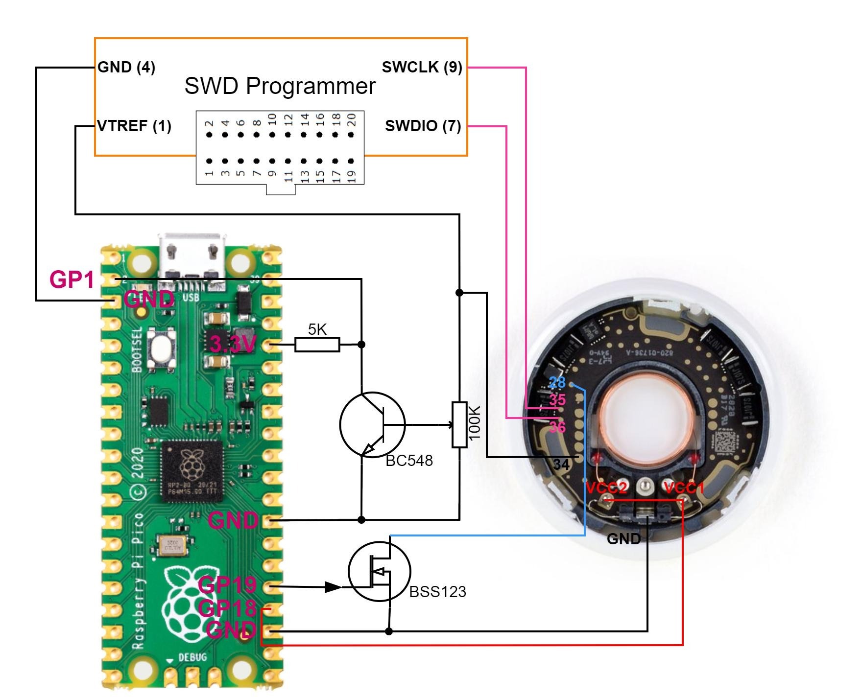 Every ground should in the end always be connected to any gnd pin on the Raspberry Pi Pico
This Diagram uses Colin o Flynn´s Pin Definitions for the airtag: Link in Useful Resources
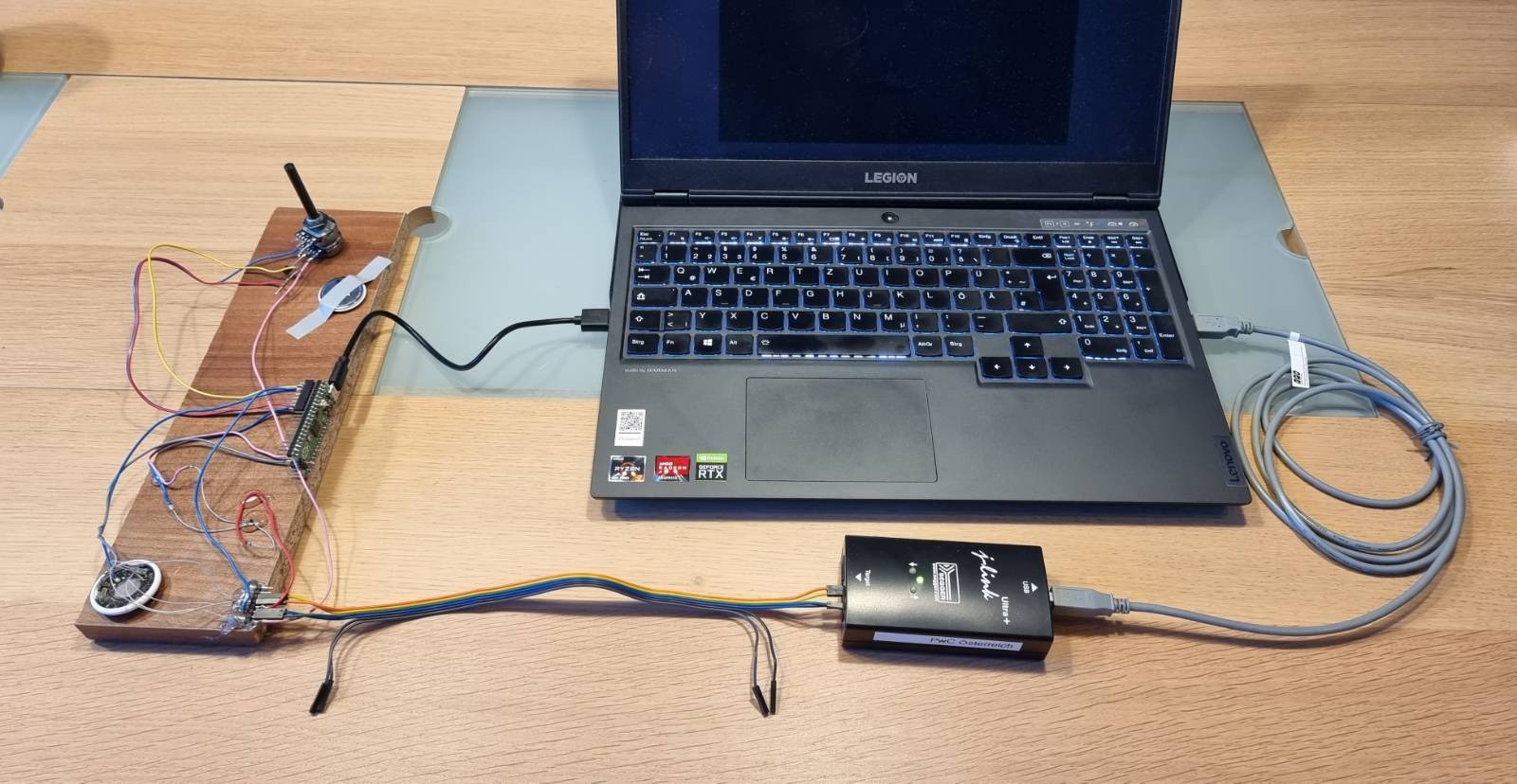
First you need to connect the Hardware for the glitch. This might take some time.
- Open up the Airtag without destroying it -> See guides on YouTube
- Build a uni-directional level shifter shifting from 1.8V to 3.3V according to the diagram above
- Connect / Solder the parts according to the diagram and test if everything works as intended
The Airtag is being powered by our Raspberry Pi Pico. If you take a quick look at the Airtag it has two distinct positive power connections that both need to be powered --> you have to solder a bridge between the contacts as they are not connected to each other.
Be extra careful, use very thin wires and max heat of 270°C to reduce chance of damaging the test pads (which fall of easily).
Due to the way the level shifter is constructed the Raspberry Pi Pico will receive 3.3 volts when the Airtag is powered down and 0.0 volts when the Airtag is powered up (1.8V are being sensed at NRF_VDD test point). If you change characteristics of the level shifter or use a prebuilt one you have to change and rebuild the Pico Firmware at
while(gpio_get(IN_NRF_VDD));
and change it to
while(!gpio_get(IN_NRF_VDD));
I used a potentiometer as resistor in the level shifter. It was set in a way to behave like cmos logic.
If you have a CMOS Logic anything over 0.606 x Nominal Voltage is considered HIGH = 1 So i set the potentiometer to activate the transistor when it receives > ~ 1.09 Volts (0.606 x 1.8V). Why is this important? It is not, but setting it up the same way will reduce the time you need for adjusting the delay in the jupyter notebook (especially if you have no oscilloscope) as the point in time where the trigger is activated will vary greatly depending on when the level Shifter considers the Airtag to be powered on (HIGH).
I used the BSS123 Mosfet because i had that laying around
If you decide to use another Mosfet - choose one that has similarly fast Turn–On Delay Time and Turn–On Rise Time to avoid having to mess a lot with the Delay specified in the Jupyter Notebook.


- some linux distro (might work on Windows with some changes)
- python 3.8+
- openocd for checking debug + dumping
- nrfjprog (J-Link only) for reset + flashing <-- might work with openocd as well
- minicom for serial monitor
- telnet enabled for dumping airtag
Software consists of 2 Parts:
- Binary / Build yourself for Raspberry Pi Pico Used to do the actual glitching on the airtag and manage delay and pulse length
- Jupyter Notebook Script running on the computer that sends Commands to Raspberry Pi Pico over Serial connection and checks with openocd if the glitch was successful.
If you can not use the pre-built binaries or need to change code:
- Get and install pico-sdk here
- Build:
export PICO_SDK_PATH=...
mkdir build
cd build
cmake ..
make
Otherwise you can just use built_binary/pico_firmware_current.uf2 for the Raspberry
To flash the Binary, longpress and hold the BOOTSEL button on the Raspberry Pi Pico and connect it via USB. Copy the built .uf2 Binary to the RPI-RP2 Mass Storage Device.
- Create & activate a Python Virtual Environment
python -m venv ./airtag-glitch
source airtag-glitch/bin/activate
- Install all needed libraries + jupyter with pip (be sure to install pyserial, not serial)
pip install jupyter tqdm pyserial
- cd into the notebook folder of the git repo and start up jupyter while in virtual environment
cd airtag-glitcher/notebook
jupyter notebook
- Connect J-Link and check if openocd command finds the testnrf.cfg config file by executing
openocd -f "interface/jlink.cfg" -c "transport select swd" -f "testnrf.cfg" -c "exit"
---------------------------------------------------------------------------------------
Errors are ok as long as config is read correctly - otherwise copy the testnrf.cfg to the correct folder
- Be sure that the current user has permissions for Serial Com Ports (for ubuntu add the user to dialout group and restart system - otherwise you have to manually chmod 777 the serial port after connecting Raspberry)
usermod -a -G dialout $USER
Important Note: First of all make sure the Airtag is not connected to any iPhone (remove Airtag in FindMy-App)
- Have the Hardware and Software set up, be in virtual environment and have jupyter Notebook open
- Connect the j-Link and the Raspberry Pi Pico via USB
- Open minicom serial to Raspberry Pi Pico:
minicom -b 115200 -o -D /dev/ttyACM0
- You will be greeted by minicom with the board having started up and ready for use:

- Start the glitch script and let it run to completion - if it interrupted and printed a success message you can skip "Setting up the delay", otherwise the configured delay was not correct or you are unlucky

If the preconfigured delays do not do the job or you used slightly different hardware - you will need to adjust the delay within the trange in the jupyter notebook at:
while True:
   for delay in trange(72500, 74000):
       set_delay(delay)
       for pulse in range(7, 9):
           set_pulse(pulse)
           glitch()
           time.sleep(0.05)
           if test_swd():
               print("Glitch successful - swd debug activated (APProtect disabled until powercycle)")
               sys.exit(0)
But what delay values to use?
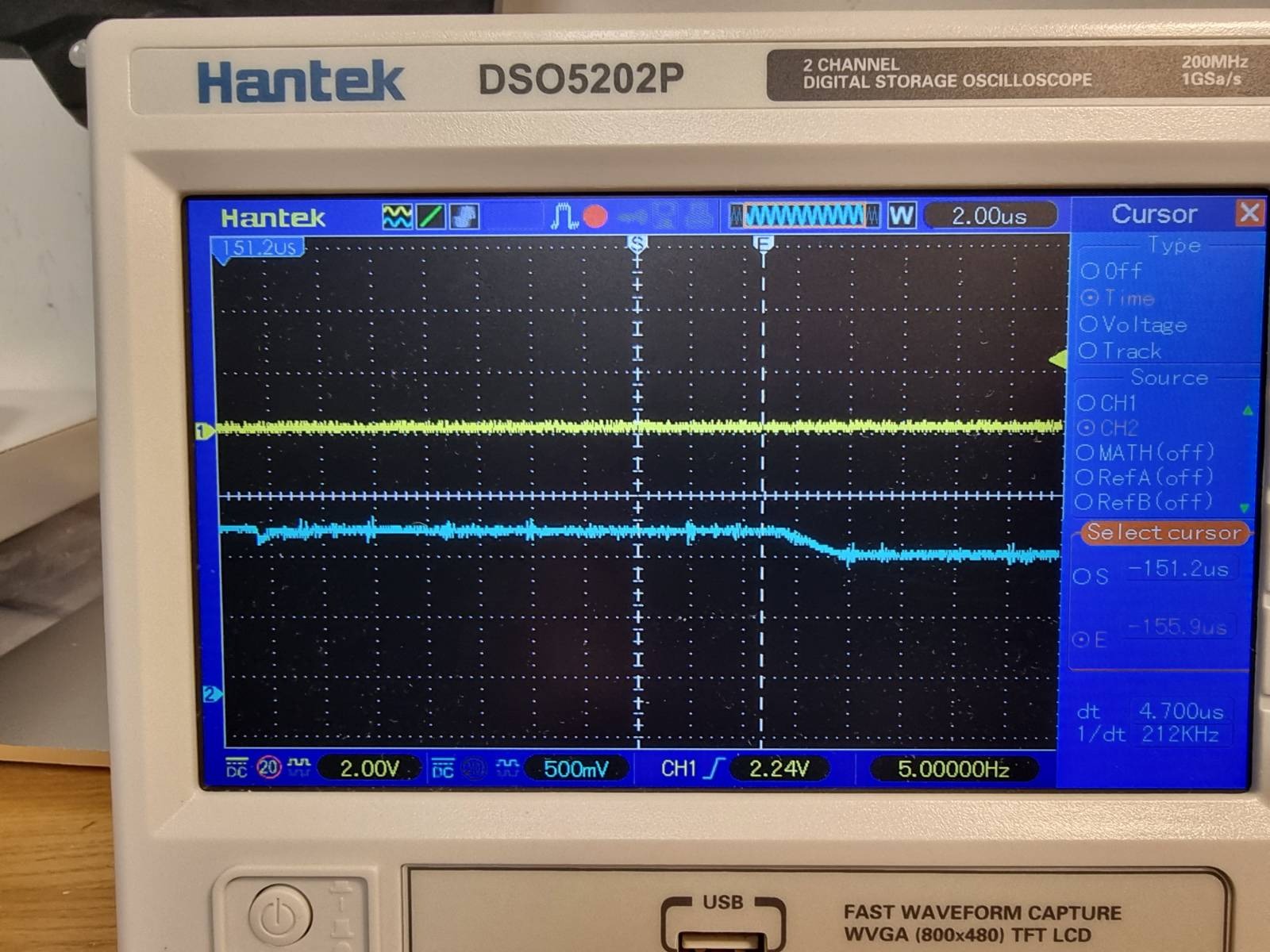
Set a long range of delay and connect Oscilloscope Channel 1 to GPIO19 (Glitch Trigger) and Channel 2 to Airtag test point 28 (CPU_Core_Voltage) while the glitch script is running.
Find when the CPU_Core_Voltage at Pin 28 slightly drops after the CPU Core being powered up. The Glitch Trigger from GPIO19 should happen just some us before this voltage drop. This does not have to be super exact as the trigger coming from pico is fluctuating a lot anyways but it should be around there.
You can now look where the trigger is coming in with regards to the voltage drop and adjust the delay higher or lower accordingly.
Picture of CPU being powered on and the subsequent small drop in voltage (attention: glitch trigger in this picture is set way too early)

Picture of the voltage drop zoomed in (glitch trigger should be happneing just a few us before this)
For more information look at Approtect bypass on NRF52 by limitedresults in "Useful Resources" below.
Basically - you will have to guess the delay. Set a broad range of delays and let it run overnight. E.g. trange(50000, 150000)
Now that we have the correct delay set we can continue after Step 5 from above
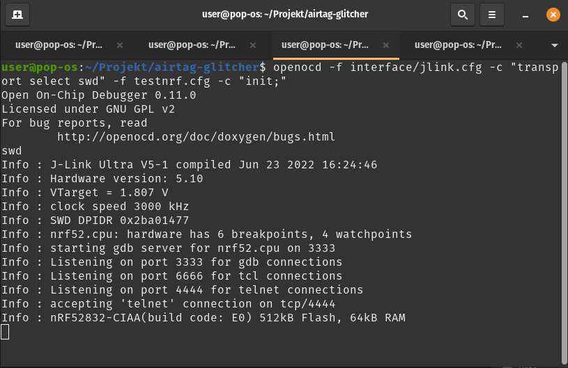
- After the successful glitch connect openocd to the Airtag
openocd -f interface/jlink.cfg -c "transport select swd" -f testnrf.cfg -c "init;"
It should look like this:
- Connect to the session via telnet
telnet 127.0.0.1 4444
- You can now issue commands e.g. reading what flash config is used
flash list
- Finally we can dump the Image of the Airtag or alternatively also read the flash banks separately
dump_image airtag_flash_real.bin 0x0 0x80000
flash read_bank 0 bank0_flash.bin
flash read_bank 1 bank1_uicr.bin
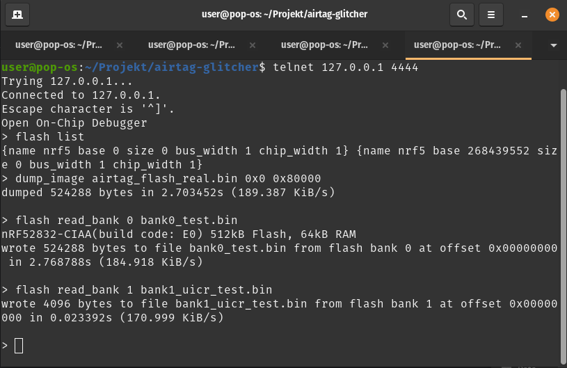
You have successfully dumped the Airtag - now you can do whatever you wish with that - happy reversing! 😎😁
DO NOT USE OPENOCD to flash an image to the airtag --> YOU WILL BRICK IT
--- this section is ommited from public viewing due to moral concerns ---
Stacksmashing´s Devcon 29 Talk about Airtags:
Airtag test point definitions by Colin O’Flynn
Approtect bypass on NRF52 by limitedresults
https://limitedresults.com/2020/06/nrf52-debug-resurrection-approtect-bypass/ https://limitedresults.com/2020/06/nrf52-debug-resurrection-approtect-bypass-part-2/
limitedresults Attacking NRF52 Blackhat2020 Slides:
Airtag general technical information by Adam Catley: