This is an ESP32 based Bluetooth metrics server for a Reebok 5.7e indoor exercise bike based on esp32-fmts-server and esp32-fmts-server-ic7. Key changes to migrate from FMTS to CSC were taken from Multi-BLE-Sensor. It does the following:
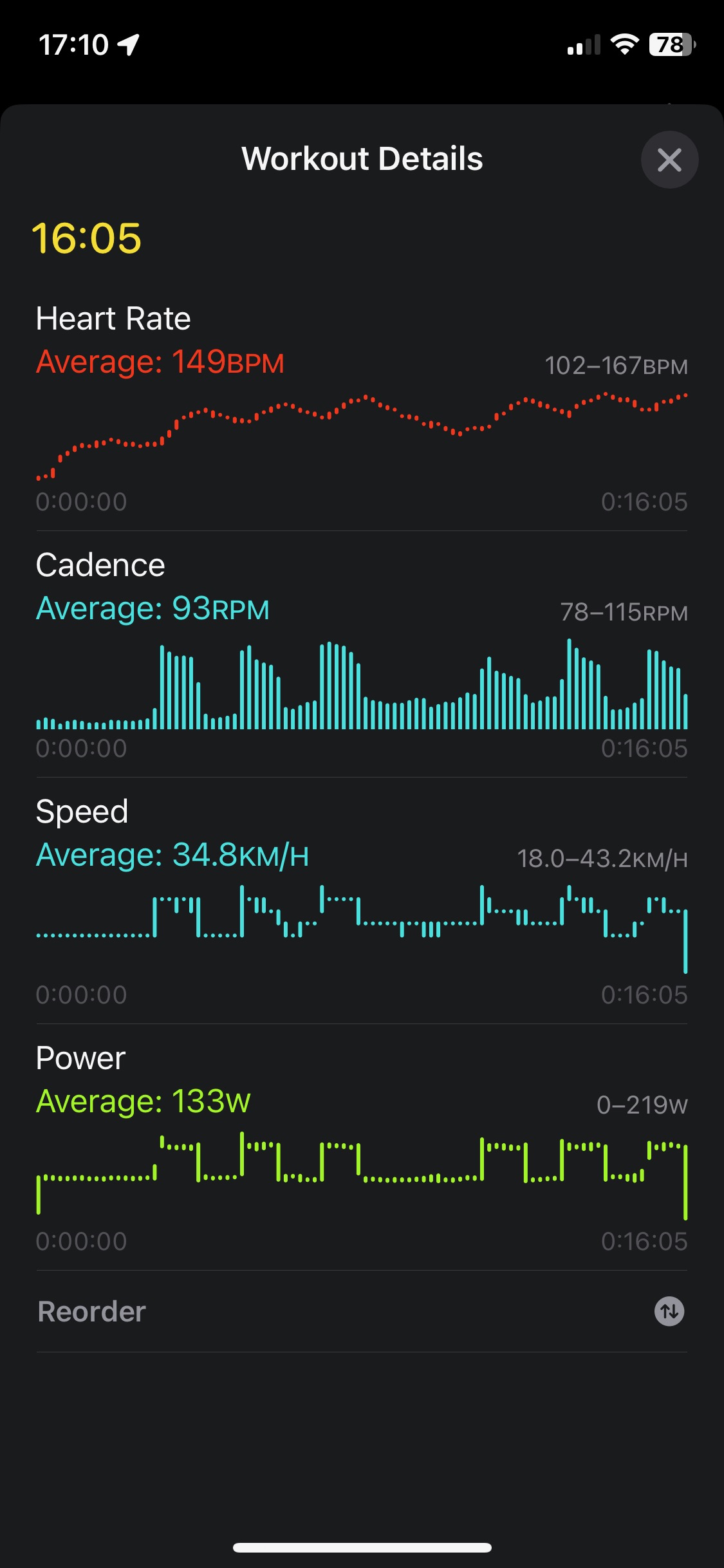
- Measures the crank rotation rate and resistance from the exercise bike.
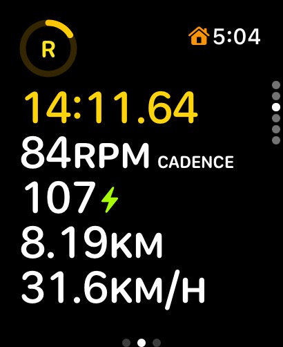
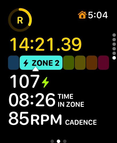
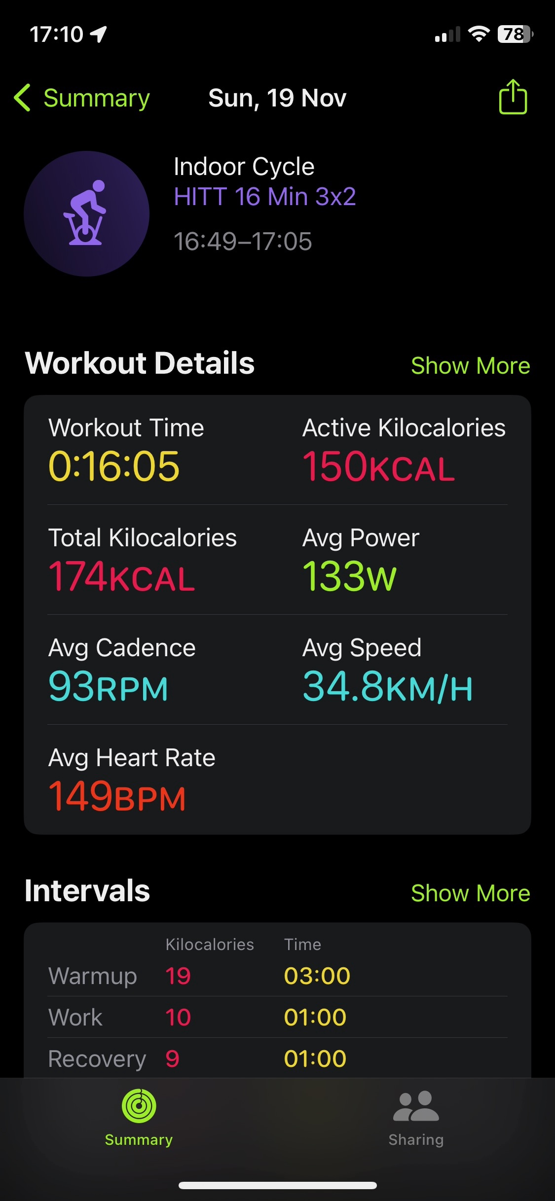
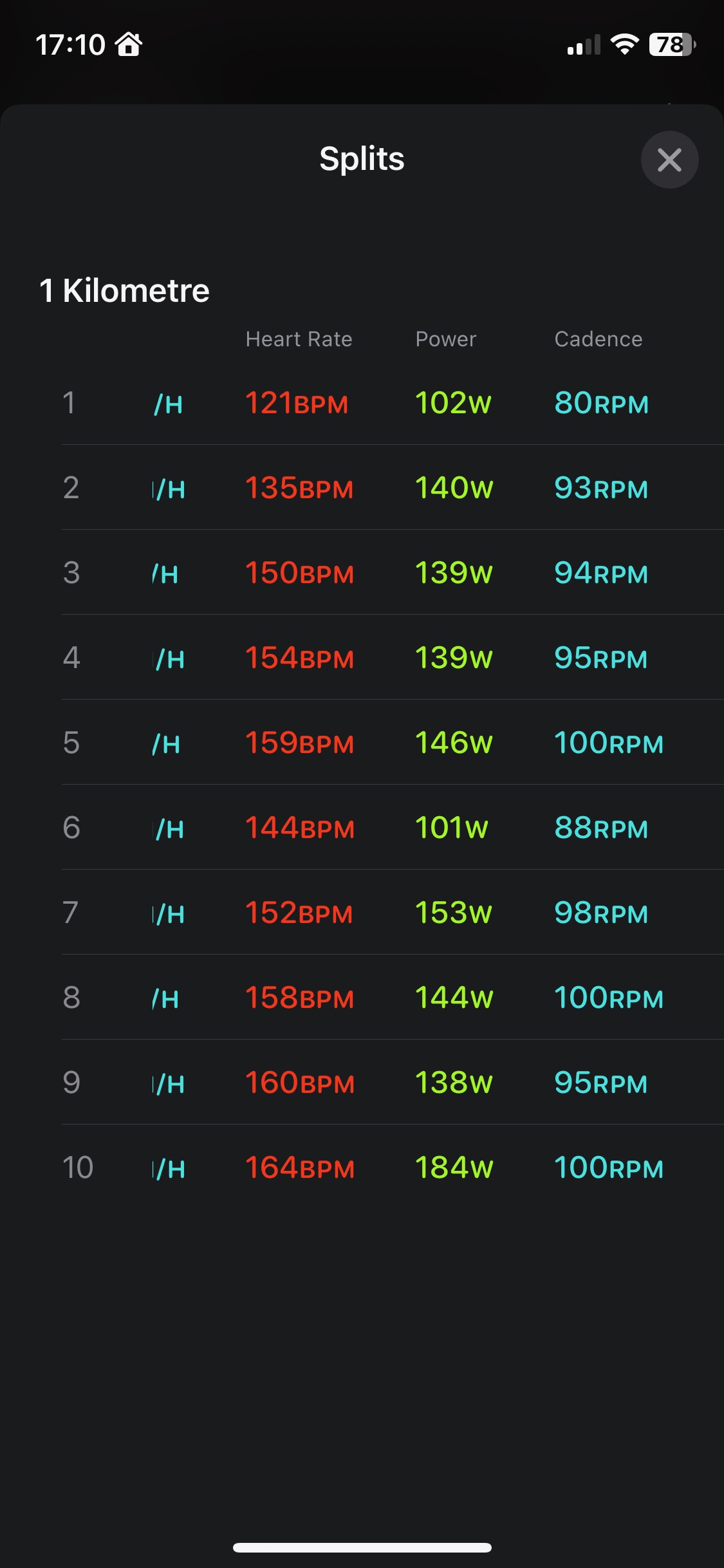
- Converts the raw measurements into key metrics such as cadence, speed, distance and power.
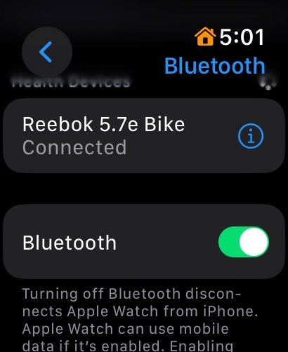
- Creates a Bluetooth server that can be connected to by a monitoring device.
The project targets the Apple Watch running watchOS 10 or later as a monitoring device.

The forked project uses the Bluetooth Fitness Machine Service (FMTS) server. Specifically it uses the Indoor Bike Data characteristic of the FTMS service. This service is currently not supported by my target of the Apple Watch running watchOS 10 as a monitoring device. There is a separate (untested) branch for this service in case it is supported by future versions of watchOS.
This branch focuses on the supported Bluetooth Cycling Speed and Cadence (CSC) service and the Cycling Power Service.
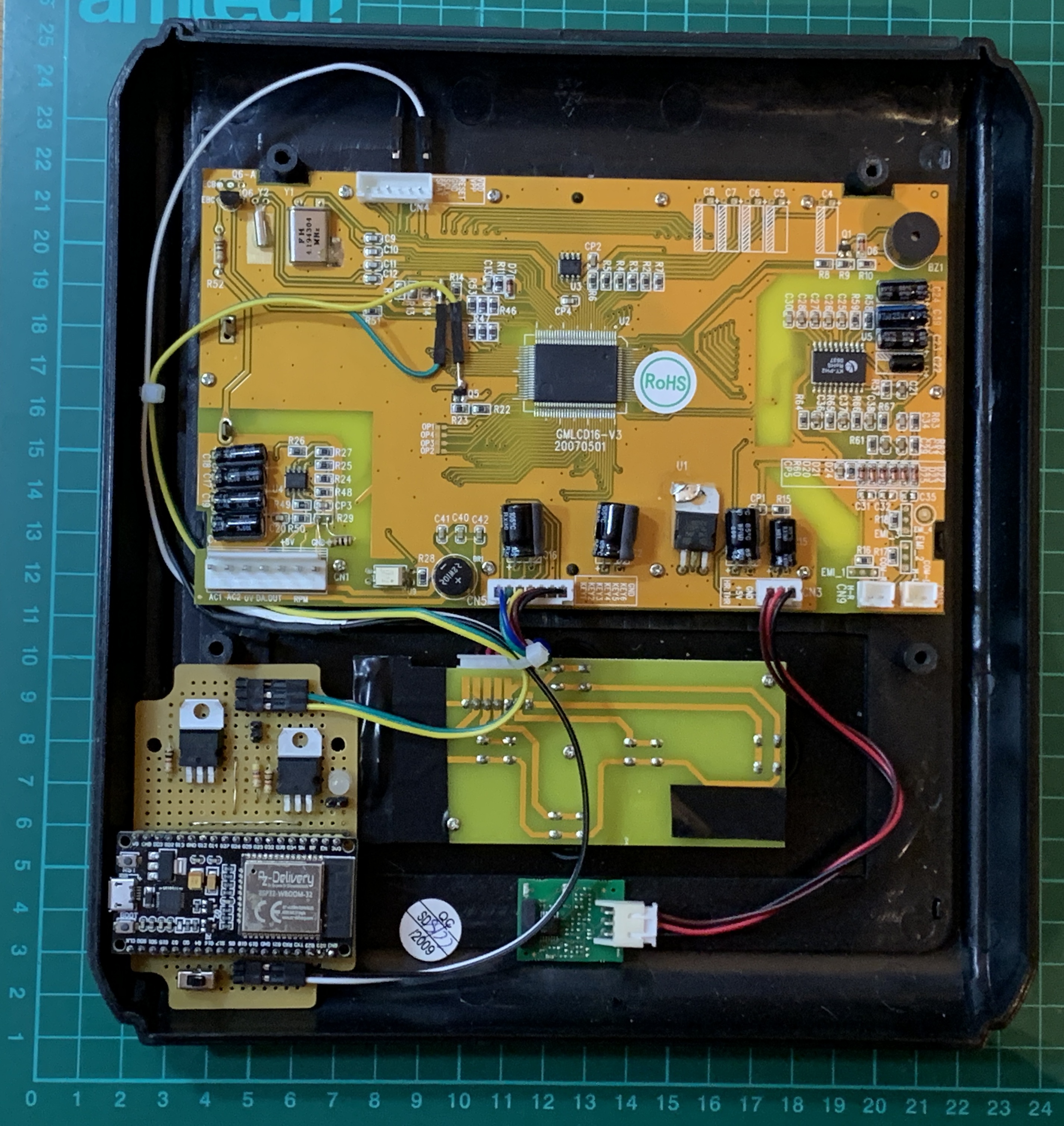
By dismantling the bike and reverse engineering the power board and the main board the general working principle of the exercise bike was determined. Cadence is measured using a reed switch, which switches a GPIO of the main MCU to ground when triggered. The electromagnet used for resistance is controlled by the power board. This modulates a rectified mains AC voltage supplied to the electromagnet using an PWM input. The PMW input is controlled from the main MCU GPIO via an optoisolator and opamp. The optoisolator output is used as an input to the opamp resulting in synchronous PMW output using a low-voltage AC signal from the power board. The main MCU is at 5V VCC.
Power for the ESP32 is taken from the interface header.
The reed switch is tapped for the cadence trigger at the MOSFET to the GPIO on the main board. A PNP transistor is used to level shift and invert the signal for digital read by the ESP32.
The electro-magnet PWM control signal is tapped for resistance at the MOSFET from the GPIO main board. An NPN transistor is used to level shift and invert the signal for analogue read by the ESP32.
Simple edge triggering is used on the reed signal, with a de-bounce delay, to count crank revolutions and crank revolution times. Wheel revolutions and wheel revolution times are calculated using a gear ratio and wheel size such that client displayed speed/distance matches the bikes display.
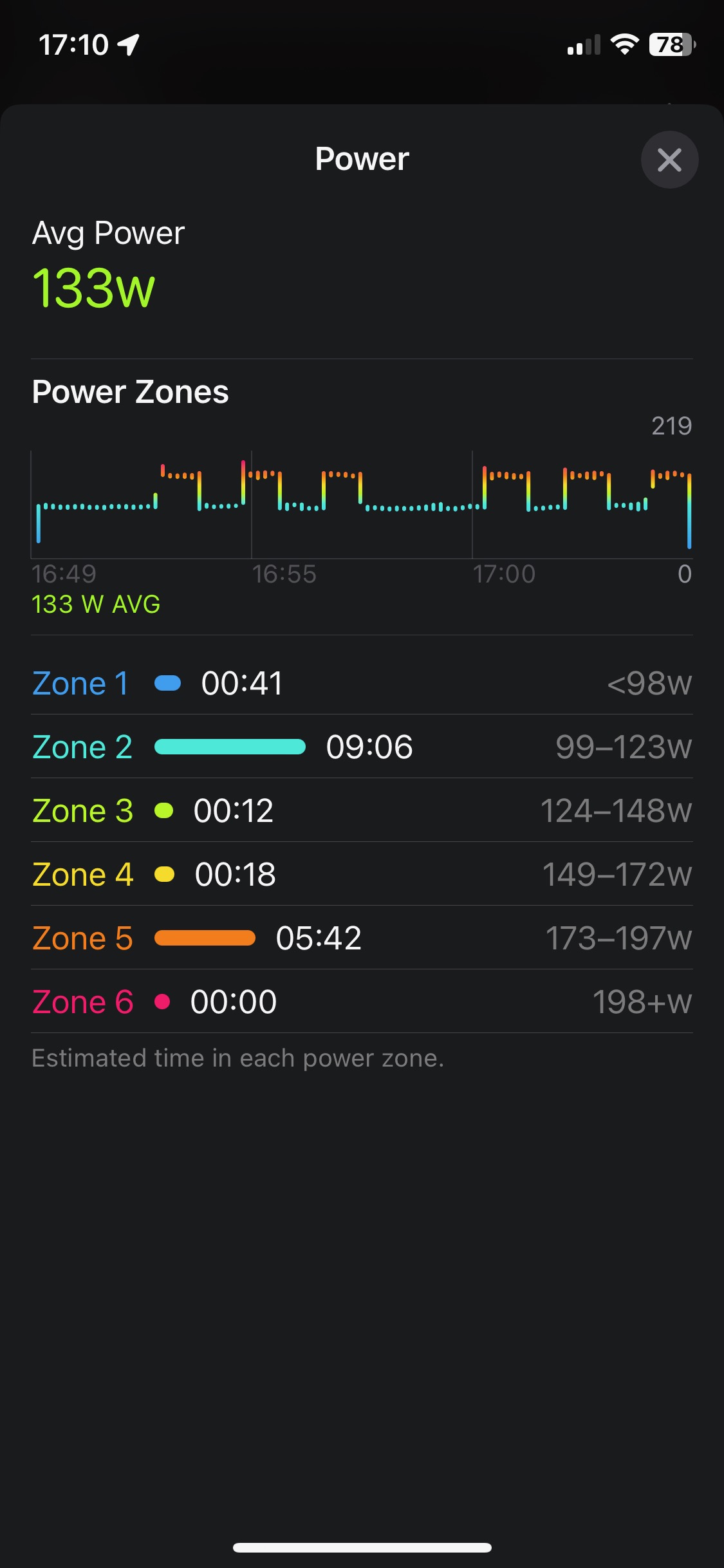
Power is calculate from duty-cycle (voltage) of the electro-magnet control signal. An empirical relationship for power as a function of cadence and duty-cycle was determined. For fixed power and cadence the duty-cycle was measured. A simple quadratic function was sufficient to model power, with coefficients determined through non-linear fitting.
Although developed for my use case this code can be easily implemented for any exercise bike and other Bluetooth clients. The simplest implementation would be an external reed sensor connecting GND directly to ESP32 GPIO (or an external hall sensor) using CSC mode (no USEPOWER) or estimated power (USEALTPWR) mode with appropriate trigger logic (USEDIRECT).
Triggering using the internal hall effect sensor of the ESP32 is also implemented, but not test in-situ. Trigger threshold (HALLTRIG) and logic would need to be adjusted for specific magnet orientation and distance from sensor.
Feature complete, final release.
- Setup toolchain [Arduino IDE v2.2.1 + esp32 (Espressif Systems) v2.0.11 / NodeMCU-32S]
- Update code header
- Compile unedited code
- Update readme
- Test flash unedited code to ESP32
- Update code for specific hardware identities [Reebok 5.7e]
- Code for Bluetooth Cycling Speed and Cadence (CSC) service cf. FTMS
- Test connect ESP32 to monitoring device
- Update code to report simulated dynamic metrics [CSC]
- Code for Bluetooth Cycling Power Service [CPS]
- Investigate bike hardware [needed crank puller]
- Identify sensor source for rotation [reed not Hall sensor]
- Assess MCU power source from exercise bike computer [5V from programming header GND/VDD]
- Access direct rotation sensor [5V pulled to GND tap reed switch (RPM) contact on main PCB]
- Identify sensor source for resistance [main PCB - optoisolator - power circuit - power board - rectified AC - triac]
- Update code to read PWM [analogueRead]
- Create prototype interface circuit from reed switch to ESP32 [TIP125 PNP common GND, base to GPIO]
- Assess power on/off with bike computer [powers up on wake, powers down on sleep]
- Access direct resistance sensor [5V 1 kHz PMW tap at MOSFET to optocoupler on main PCB]
- Create interface board [proto board, socketed ESP32, power/sensor in headers, scope test points, strain relief, VCC in switch for USB power/debug]
- Fix broken resistance function [burnt out resistor to optocoupler out]
- Assess power on/off with bike computer [programming header always powered]
- Create prototype interface circuit from PMW signal to ESP32 [TIP120 NPN, base to PWM]
- Calculate primary resistance metric as PWM duty-cycle (D) [100% = high resistance, 0% = no resistance]
- Finalise interface board [implement PWM circuit, insulation, robust physical mount]
- Implement sleep timer [deep sleep after inactivity, wake on crank sensor]
- Measure magnet duty-cycle at given cadence [80,100,120] and power [60, 100, 150, 190, 240, 280]
- Finalise code to report correct cadence [notify every 2 seconds]
- Report estimated power based on speed only [not very accurate]
- Report duty-cycle as power to collect data for correlation [manual]
- Added crank trigger via build in hall effect sensor [because its there]
- Added provision for simple reed trigger [GND - REED - GPIO]
- Reverse engineer power function: P = f(D,C) [implemented]
- Decide to use measured, P = f(D,C), or estimated, P = f(S), power [use measured]
- Fix bug relating to incorrect crank time after integer rollover [use lastTrigger to calculate lastCrankK]