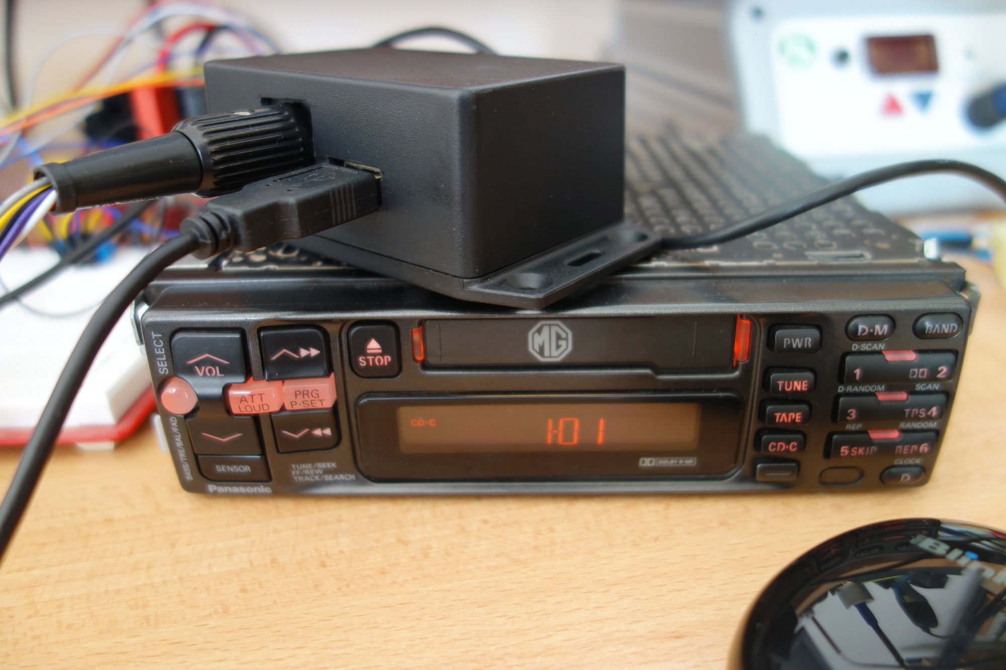
The project is a combination of hardware and software to emulate a Panasonic CX-DP60 CD Changer (CDC), allowing early 1990s car radios to use the CD inputs as an auxilary. Tested with a Panasonic CQ-LR2450A (from an MG RV8) but should work with others from the same era.
Without a CDC connected the radio ignores changing to the CD input, hence the need to emulate its presence. This isn't a new idea; others have created emulators for newer CDCs (see CDCEmu, VAG CDC Faker, etc.) but these don't work with older radios.
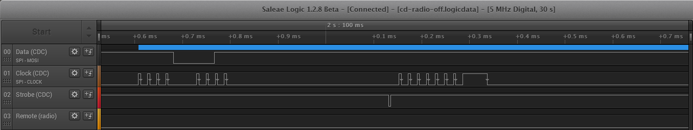
I started by looking at the DP60's schematics (actually, I started with CDCEmu, which didn't work, so I rolled up my sleves and did this) and recording the traffic with a Saleae Logic. The radio's remote commands look to be using a variant of the NEC protocol whereas the CDC's data is a byte orientated synchronous serial stream:
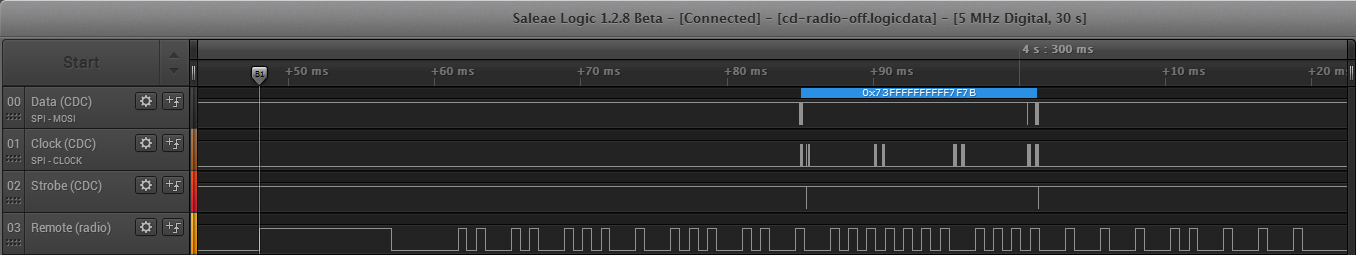
A close-up of the CDC's serial data can bee seen here, with a Logic capture of the traffic between the CDC and radio here (note that the Logic hardware isn't required to view the capture).
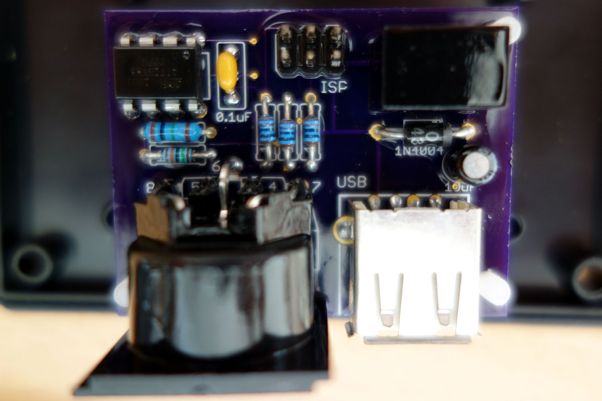
It's not necessary to understand or fully decode the communication, just to recognise and replay. The documented source and schematic are available above, but for anyone wishing to simply build it, it's enough to order a PCB (either from the Eagle project files, the resulting Gerbers, or direct from OSH Park) and program the flash (via the ISP connector on the board using the prebuilt firmware and any low-cost programmer). It was designed to be built with nothing more than a regular soldering iron.
Parts can be ordered from Farnell, Mouser or any other componment supplier (the BOM is available here, which can be sent directly to Farnell's BOM upload). The finished project has a USB connector to power a Bluetooth or DLNA receiver (tested with an Arcam miniBlink). A conformal coating was added to protect the board from any moisture.
When powered on the board sends 0x73FFFFFFFFFF7F7B every 40ms to the radio (on the data, clock and strobe lines; see sendBytes()) to say there is a CDC connected. When the radio switches to the CD input, with either a 0x08 or 0xA4 command (see ISR(INT0_vect)) the board then starts sending 0x33FFCF81CF7F7F3B, meaning the first CD is playing track one (it probably contains time data and so on, but it's not necessary to know, just to replay what was captured). The only other radio command understood is 0x10, sent when switching back to the tuner or cassette, or when powering off, to which the response is 0x13FFFFFFFFFF7F1B (without which it's not possible to turn the radio off).
Output from the emulator to the radio is bit banged, with timing close enough to the DP60 that the radio is happy (but simplified; the real timing is much more complex, just not required). Input to the emulator from the radio uses a hardware interrupt (INT0) and one of the hardware timers (TIMER1) to decode the remocon signal.
Send delays would be better implemented using the ATtiny's other hardware timer, then the board could drop into low-power mode (not really needed but is the correct way of doing things). Multiple audio sources could be supported by changing virtual CDs (with the circuit extended so the ATtiny switches analogue sources).