ArduJtag is a lightweight and easy-to-use library for interfacing with JTAG devices using Arduino boards. This library provides a way to communicate with JTAG compatible devices. It is based on the JTAGduino project and was developed during the work on the Diving into JTAG protocol article and used to study this protocol
- Control JTAG pins (TCK, TMS, TDI, TDO) directly from your Arduino
- Simple API for sending and receiving data
- Support for JTAG sequences and operations
- Configurable communication speed
-
Clone this repository into Arduino/Libraries or use the built-in Arduino IDE Library manager to install a copy of this library.
-
Include in your sketch
#include "Jtag.hpp"Install ArduJtag using the platformio library manager in your editor, or using the PlatformIO Core CLI, or by adding it to your platformio.ini as shown below:
[env]
lib_deps =
    ArduJtag
[env]
lib_deps =
https://github.com/Zamuhrishka/ArduJtag.gitTo demonstrate the use of this library, I will show how to interact with the STM32F407 microcontroller via the JTAG interface. This microcontroller contains 2 TAP modules connected in series: BoundaryScan and Debug:
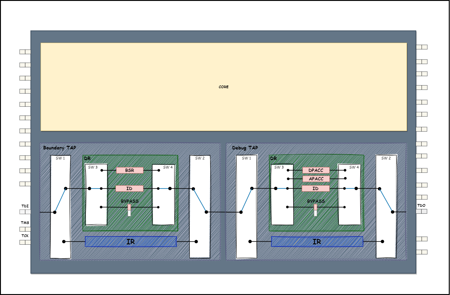
The size of the IR register for the BoundaryScan TAP is 5 bits. For the Debug TAP, it is 4 bits.
For writing into the IR register, the following function is used:
  /**
   * \brief Send an instruction through the JTAG IR (Instruction Register)
   *
   * \param instruction The instruction code to be sent
   * \param length The length of the instruction in bits
   */
  void ir(uint16_t instruction, uint16_t length);
Let's look at what arguments need to be passed to this function to set the BYPASS instruction in the BoundaryScan TAP, and the IDCODE instruction in the Debug TAP.
Considering the arrangement of the BoundaryScan TAP and Debug TAP in the scan chain: BoundaryScan TAP is first - Debug TAP is second, and the fact that in JTAG data is transmitted least significant bit first, it turns out that for our purpose we need to write in the IR BoundaryScan TAP the value 0x1F (0b11111), and in the IR Debug TAP - 0x0E (0b1110). As a result, the bit sequence that needs to be set on the TDI line looks like this (remembering that in JTAG data is transmitted least significant bit first):
TDI: 011111111The values of the arguments:
  uint16_t instruction = 0;
  uint16_t length = 0;
ir(instruction = 0x1FE, length = 9);For writing into DR register the next function used:
  /**
   * \brief Send data through the JTAG DR (Data Register)
   *
   * \param data Pointer to the data array to be sent
   * \param length The length of the data in bits
   * \param output Pointer to the buffer where the response will be stored
   */
  void dr(uint8_t *input, uint32_t length, uint8_t *output);
The formation of the input buffer occurs as follows, suppose you need to send the following bit sequence:

Then the input array should look like this:

The same transformation applies to the output array.
Let's consider a more specific example. Suppose it is necessary to send the following bit sequence into the DR register:

Then the input array should look like this:

  uint8_t input = {0x02, 0x00, 0x40, 0x01};
  uint8_t length = 0;
  uint8_t input = {0x00, 0x00, 0x00, 0x00};

void dr(input, length = 27, output);To form an arbitrary JTAG packet, the following function is intended:
/**
   * \brief Perform a sequence of JTAG operations (a series of bit manipulations on TMS and TDI
   *        reading TDO)
   *
   * \param n Number of operations in the sequence
   * \param tms Array of TMS values for the sequence
   * \param tdi Array of TDI values for the sequence
   * \param tdo Pointer to the array where TDO values will be stored
   * \return JTAG::ERROR Status of the sequence operation
   */
  JTAG::ERROR sequence(size_t n, const uint8_t tms[], const uint8_t tdi[], uint8_t *tdo);
The principle of forming arrays tms, tdi, tdo is exactly the same as for the input and output arrays described in the previous section.
More examples of using this library can be found in examples.
Bug reports and/or pull requests are welcome.
This software is provided 'as-is', without any express or implied warranty. In no event will the authors be held liable for any damages arising from the use of this software.