some problems about rfid_Cloner_2 (buttons) #4
Comments
|
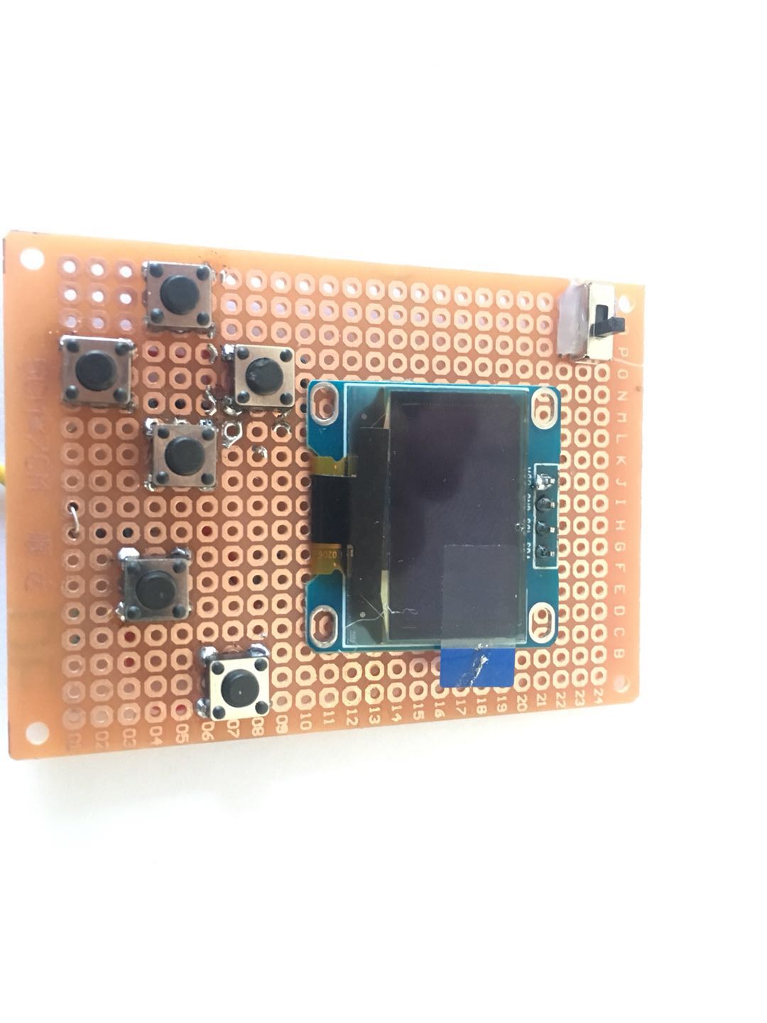
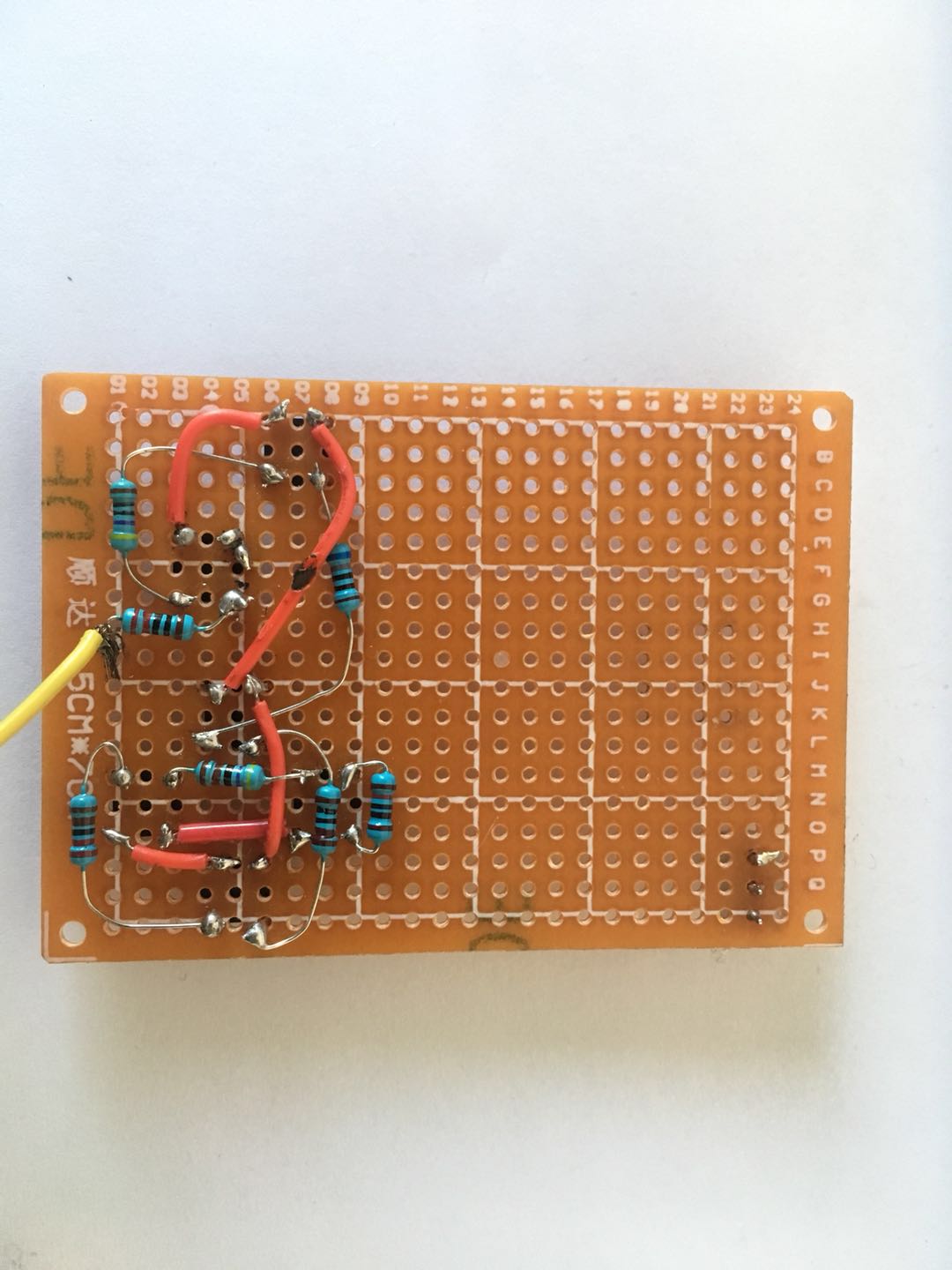
Hello, in the GUI.cpp there's the following line: You could change it into the following: After uploading the code and turning on the device it should look like this: Make sure to test it with battery instead of USB cable (it affects the analog input reading). Only 1 (analog) pin is used to receive input of all the buttons (using voltage dividers). It would be all fine but the battery voltage is decreasing over time and the readings when specific buttons are pressed also decrease. To tackle that problem I added 10K resistor that is constantly dividing voltage (producing constant readings - "51" visible on the image above), it allows to constantly monitor the voltage and automatically calibrate the buttons in real time. I would do the following in this case:
ButtonMap buttonMap[BUTTON_COUNT] = {
 50.5, BUTTON_NONE, "NONE", [](){},
 100.0, BUTTON_UP, "UP", [](){},
 191.0, BUTTON_DOWN, "DOWN", [](){},
 315.0, BUTTON_LEFT, "LEFT", [](){},
 449.0, BUTTON_RIGHT, "RIGHT", [](){},
 629.0, BUTTON_YES, "ACCEPT", [](){},
 871.0, BUTTON_NO, "DECLINE", [](){},
}; |

|
Thank you very much. But yesterday when uploading firmware accidentally broke oled, there is no more simple way like rfid_Clone_1, copy cloning, through the led reminder and two buttons (one to read card and one to write card) way to achieve. Based on esp8266 |
|
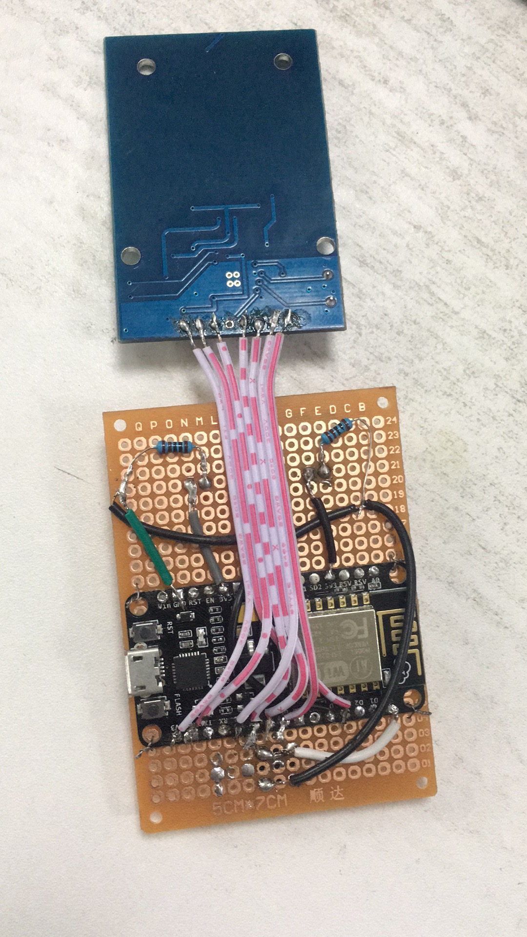
It would be kind of waste to not use display after all this soldering:p, are you sure that the display is not going to work? Did it get like physically broken? (I remember that when I was playing with display like this I was almost sure it won't work anymore but it turned out the connections were wrong). You could use the first version with NodeMcu and it should work, what you'd have to do is:
#define RST_PIN 8
#define SS_PIN 10
replace it with: #define RST_PIN D3
#define SS_PIN D8
#define BTN_PIN D0
#define LED_YELLOW_PIN D4
#define LED_GREEN_PIN SD3
Zener diodes used in the first version won't be required because NodeMcu has 3.3V pin. |
|
I change the code with Cloner_1 . But uploading firmware , there is an error, SD3 was not declared in this scope . and how to use D4 and SD3 to connect LEDs . |
|
My bad, SD3 is not defined, you could use pin 10, which is SD3: #define LED_GREEN_PIN 10 //SD3Just in case if it is confusing why pin 10 is "SD3" here's a diagram: link |
|
I just pressed some keyboard shortcut (or touched the touchpad...) and closed the issue by accident |
|
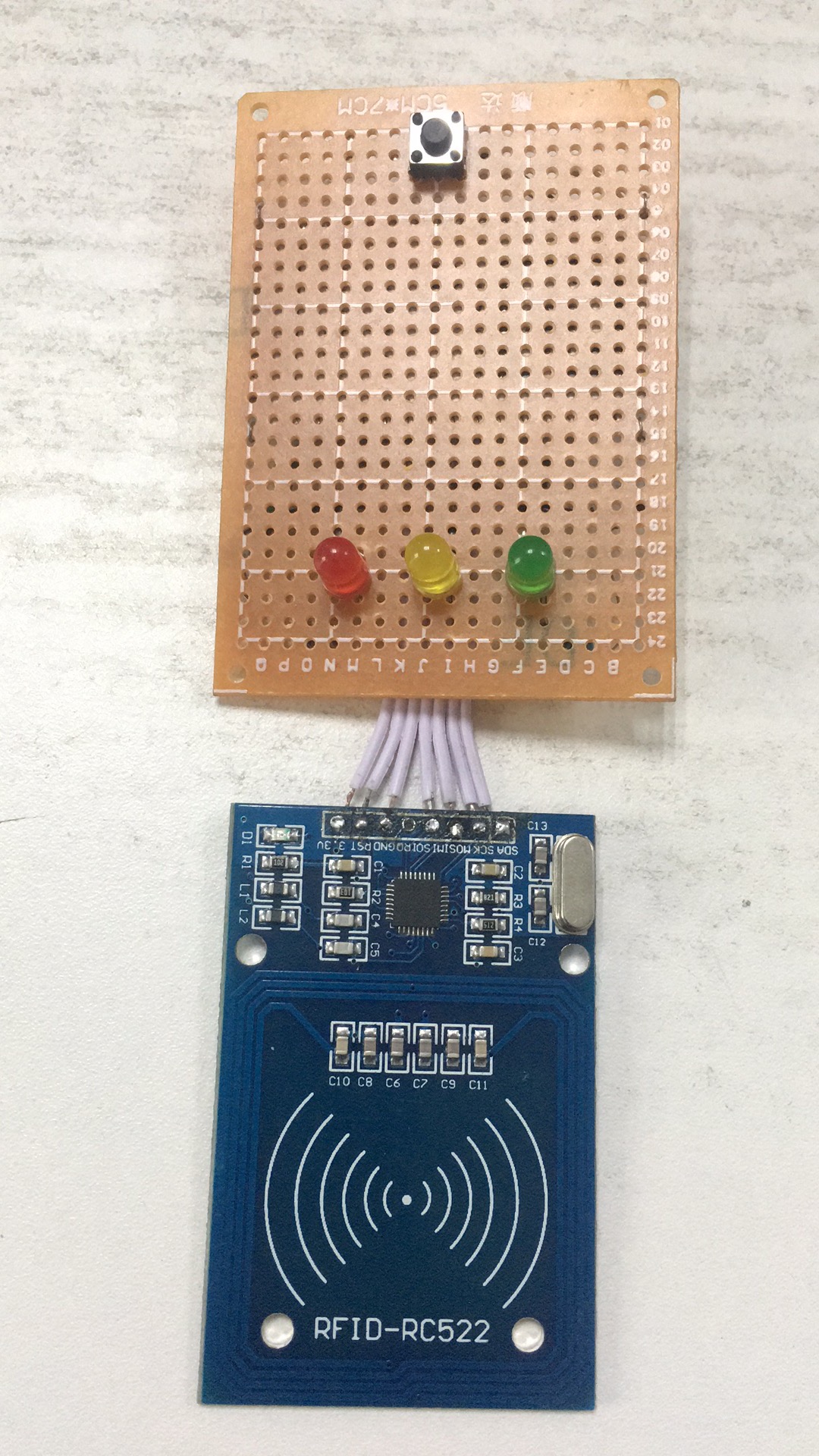
Thank you. Another problem is how to connection the leds and button with esp8266 |
|
You could take a look at the first version wiring and connect it the same way but to different pins
|
|
If I am too stupid. I checked that all the link lines were correct, the green and yellow lights were on and the red light was on, but when I pressed the button there was no response, and I now wonder if my 8266 board was broken, although the firmware upload was fine. |
|
I just found out that I didn't include What I would do is to verify that everything is connected properly:
#define BTN_PIN D0
#define LED_YELLOW_PIN D4
#define LED_GREEN_PIN 10

void setup() {
  pinMode(BTN_PIN, INPUT_PULLUP);
  pinMode(LED_YELLOW_PIN, OUTPUT);
  pinMode(LED_GREEN_PIN, OUTPUT);
  Serial.begin(9600);

}

void loop() {
  delay(500);
  digitalWrite(LED_YELLOW_PIN, HIGH);
  digitalWrite(LED_GREEN_PIN, HIGH);
  delay(500);
  digitalWrite(LED_YELLOW_PIN, LOW);
  digitalWrite(LED_GREEN_PIN, LOW);

  bool button_state = digitalRead(BTN_PIN);
  Serial.println("Button state is:" + String(button_state));
}
It should toggle both LEDs every half second and print the state of the button every 1 second (that can be read in Arduino IDE -> Tools -> Serial Monitor)
constexpr uint8_t RST_PIN = 9;          // Configurable, see typical pin layout above
constexpr uint8_t SS_PIN = 10;         // Configurable, see typical pin layout above
into: constexpr uint8_t RST_PIN = D3;
constexpr uint8_t SS_PIN = D8; After uploading that example you'll have to open serial monitor and present a card to the rfid reader module, information about the card should be displayed in the serial monitor. |
|
Thank you very much. You're responding so quickly. But don't you sleep? it's supposed to be 1: 00 in the morning in Britain. take care |
|
I just noticed that I made another mistake at the: This is wrong: SCK should be D5 and SS should be D8, MISO should be D6 and MOSI should be D7, sorry about it... Btw usually go to sleep around 2-3am, just a sleeping pattern like that |

|
It doesn't work. I decided to buy a arduino nano board to try. |
|
If you'd like to try to make it work with esp then just let me know on discord (michalmonday#3687), I'm sure something can be done... |
|
Because I can't write C ++, I want to try it with micropython. |
|
Sorry for my english not good. I'm using google translate to comment here. Why do you have to use resistors for buttons? Why don't we fight the esp pins directly? |
|
Hi, thanks to resistors (that act as voltage dividers) all the buttons can be read by using a single pin (as seen on image below). This project used a display and a RFID module, both using a lot of pins. But I think that using an input shift register would probably be a better solution, mostly because the voltage differs depending on the battery level, I tried to take that into account in the code (by scaling expected voltage ranges for each button based on baseline voltage level) but I'm not sure if it's a robust method, it seemed to work in my case though.
|

I don't know what reason I confirm and delete buttons are not sensitive,Use the resistor has direction requirement?
The text was updated successfully, but these errors were encountered: